18
1
Writing to these locations is ignored. No error will occur.
NOTES
1.
All digital inputs that were not allocated as pulse inputs will be automatically configured as status inputs.
2. A digital input allocated for the external demand synchronization pulse or time synchronization pulse will be automatically
configured as a pulse input.
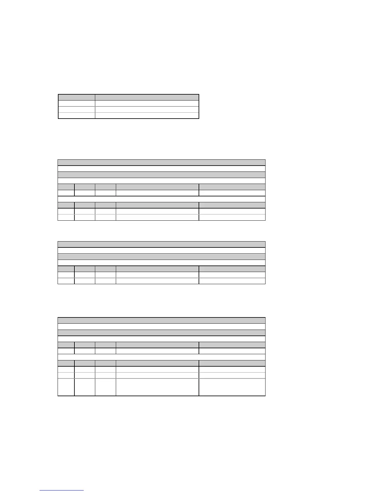
Table 4-27 Digital Inputs Allocation Mask
Bit number Description
0 Digital input # 1 allocation status
1 Digital input # 2 allocation status
2-7 Not used
Bit meaning: 0 = input not allocated, 1 = input allocated to the group
4.11 Timer Setup
Table 4-28 Read Request
Message type (ASCII)
‘E’
Message body (hexadecimal)
Request
Field Offset Length Parameter Range
1 0 2 Timer ID 0-1 = timer #1-#2
Response
Field Offset Length Parameter Range
1 0 2 Timer ID 0-1 = timer #1-#2
2 2 4 Timer interval, sec 1-9999, 0 = timer disabled
Table 4-29 Write Request
Message type (ASCII)
‘e’
Message body (hexadecimal)
Request/Response
Field Offset Length Parameter Range
1 0 2 Timer ID 0-1 = timer #1-#2
2 2 4 Timer interval, sec 1-9999, 0 = disable timer
4.12 Pulsing Setpoints
Table 4-30 Read Request
Message type (ASCII)
‘G’
Message body (hexadecimal)
Request
Field Offset Length Parameter Range
1 0 2 Pulse output ID 0-1 (see Table 4-32)
Response
Field Offset Length Parameter Range
1 0 2 Pulse output ID 0-1 (see Table 4-32)
2 2 2 Output parameter ID see Table 4-33
3 4 4 For energy pulsing =
number of unit-hours per pulse,
otherwise - permanently set to 0
0-9999

 Loading...


