54
Registers at offsets +0,+1, +4 to +6, and +11 are applicable only for waveform log records. For real-time waveforms these are
read as zeros.
1
Timestamp is given in local time in a UNIX-style time format: it represents the number of seconds since midnight
(00:00:00), January 1, 1970. The time is valid after January 1, 2000. Record timestamp shows the time for the last sample
point in the waveform record.
To convert digital samples to their analog equivalents in input measurement units (volts, amps), the following scaling should be
applied:
SCALE_DIGITAL
2SCALE_ANALOG)OFFSET_ZEROSAMPLE_DIGITAL(
]Amps/Volts[SAMPLE_ANALOG
××−
=
NOTES
1. If a record is requested when the log file is empty, the record is reported with all zeros and bits 8 and 15 in the status
indication word being set to 1.
2. Phase voltage will be line-to-line voltage in 3OP2 and 3OP3 wiring modes, and line-to-neutral voltage in other
configurations.
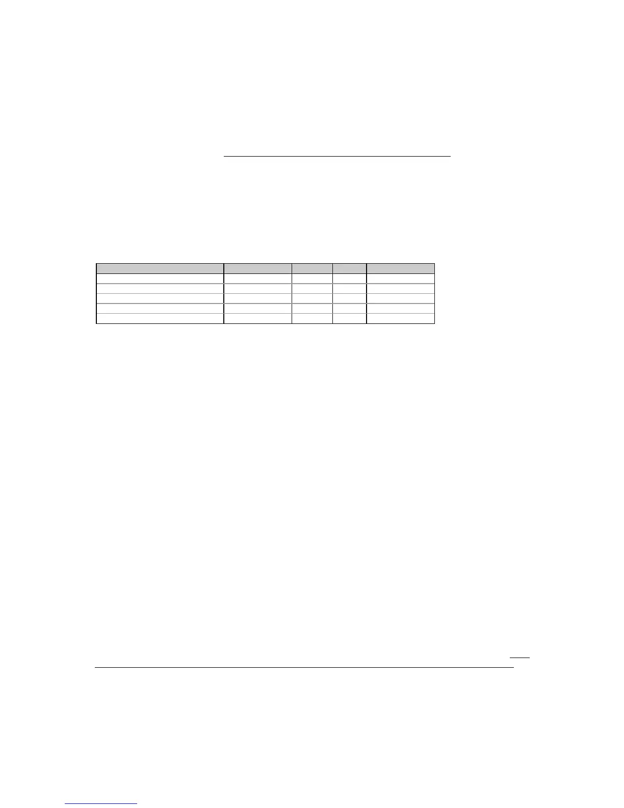
Table 5-37 Waveform Samples Registers
Parameter Register Type R/W Range
Waveform sample point #1 0xD000 INT16 R 0 to 1023/8191
Waveform sample point #2 0xD001 INT16 R 0 to 1023/8191
Waveform sample point #3 0xD002 INT16 R 0 to 1023/8191
... ...
Waveform sample point #512 0xD1FF INT16 R 0 to 1023/8191
Through these registers you can capture and read the real-time waveforms (4 cycles x 128 samples per cycle),
and the recorded historical waveform logs - the Waveform log #1 (16 cycles x 32 samples per cycle records), and
the Waveform log #2 (4 cycles x 128 samples per cycle records). The waveform samples are read via the register
window 0xD000-0xD1FF (see Table 5-37) that can map a record for a single input channel (voltage or current
waveform on either phase). To reload this window with a sampled waveform, a corresponding waveform header
window should be accessed (see Table 5-35).
Real-time Waveform Capture
The real-time waveforms can be captured simultaneously on both voltage and current channels for a single
phase. To capture two waveforms on a selected phase, the first register (at offset +0) in the voltage waveform
header window for this phase should be accessed by reading this register or by reading the entire header window.
Before responding to your request, the instrument reloads both the waveform header and waveform samples
window with data corresponding to the voltage waveform. Data in these windows does not change until the first
(command/status indication) register in either of the waveform header windows is read.
To reload the waveform header and samples windows with the current waveform data, read the first register in the
current waveform header window for the same phase.
To capture and read waveform data on another phase, repeat the above steps for the phase you want to access.
Historical Waveform Log
The historical waveform logs contain waveform records sampled at high (128 samples per cycle in Waveform log
#2) or lower sampling rate (32 samples per cycle in Waveform log #1) that are captured and logged to a file on
some event triggers. Each record contains six waveforms of voltage and current on three phases.
Recorded waveforms are mapped and accessed through register windows in the same manner as the real-time
waveforms (see above). On log files organization and managing, see Section 3.3, Configuring and Accessing Log
Files. Before reloading waveform window registers with data for a selected channel, the required record must be
obtained from the log file to the communications buffer. This is made automatically when you reload the voltage
waveform on phase L1, i.e., when you read the register at offset +0 in the voltage waveform header on phase L1
for the corresponding log file. Data in this buffer does not change until you read this register once again. Each
time you access this register, the next record is read form the file and locked to the communications buffer. To
reload waveform windows with data for the current channel or with data for another phase, read the
command/status indication register in the voltage or current header window for the corresponding channel.
Waveform log files are accessed in a circular manner. When the last record in the file is being read, bit 0 in the
status indication register in the waveform header windows is set to 1. If you continue reading after the end of a

 Loading...


