Appendix B Programmable Parameters 149
Iaux max = 1.2 × Auxiliary CT primary current [mA/A]
Pmax = (Imax × Vmax × 3)/1000 [kW] @ Wiring mode 4Ln3 or 3Ln3
Pmax = (Imax × Vmax × 2)/1000 [kW] @ Wiring mode 4LL3, 3OP2, 3dir, 3OP3,
or 3LL3
Á Power readings with a decimal point are displayed in MW, Mvar, MVA.
 The actual frequency range is 45.0 - 65.0 Hz
à The date format can be customized.
Ä New absolute value (lag or lead).
Å Release limit not used.
Æ Operate limit for the voltage disturbance trigger specifies the voltage deviation allowed
in percentage of nominal (full scale) voltage, which refers to line-to-line voltage in a
3DIR wiring mode, and to line-to-neutral voltage in other modes. The nominal voltage is
120V RMS for instruments with the 120V input option, and 380V RMS for instruments
with the 660V input option.
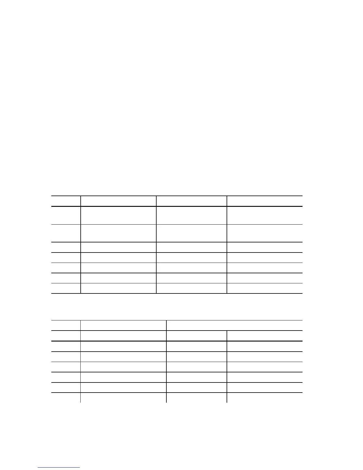
Table B-8 Setpoint Conditions
Label Operate condition Release condition Limits
GE Greater or equal (over
operate limit)
Less or equal (under
release limit)
Both limits active
LE Less or equal (under
operate limit)
Greater or equal (over
release limit)
Both limits active
Eq Equal Not equal Release limit not used
nE Not equal Equal Release limit not used
On ON OFF Both limits not used
OFF OFF ON Both limits not used
nEU NEW min/max value n/a Both limits not used
Table B-9 Setpoint Actions
Action type Action target
Label Description Range Description
nonE No action nonE No target
SEt.E Set user event flag FLG.1 - FLG.8 Flag number
rES.E Reset user event flag FLG.1 - FLG.8 Flag number
rEL Operate relay rEL.1 - rEL.4 Relay number
Inc.C Increment counter Cnt1 - Cnt8 Counter number
dEc.C Decrement counter Cnt1 - Cnt8 Counter number