6 Installation of Options
142
CL4NX/CL6NX Service Manual
14
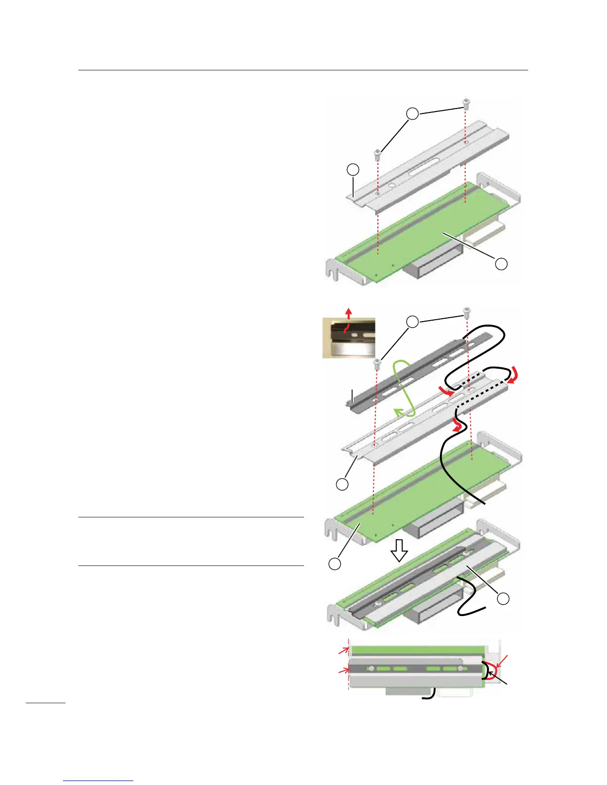
Remove two screws (print head) and
the head cover
from the
print head
0.
15
Attach the UHF (short) antenna
assembly onto the RFID head cover
as shown in the picture.
Insert front part of UHF (short) antenna assembly
through the rectangle opening of the RFID head
cover.
Route the antenna wire accordingly.
16
Attach the RFID head cover using
two screws (print head)
removed in
step 13.
Align the edge of the RFID head cover
carefully to the side of the print head
0 as
shown. Then fix the position using the screws.
The print head assembly is known as
RFID print head assembly
in the later steps.
Note
Make sure that the loop of the antenna wire is as
short as possible.
11
20
19

 Loading...


