ERECTION AND DISMANTLING
22
V23C_09.13
SC4000 Pos 4
13-0994-803-1C
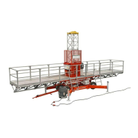
Drawing 4.13. Plat-
form section as a
side plat form.
Drawing 4.14. Chassis electric box.
5.
Assemble the rst mast section. Use
only screws delivered by the manu-
fac turer. Tighten the screws 350
Nm.
6. Connect the supply cable (400 V/ 16
A 5-poles) to socket X1 of the chassis
electric box.
7.
Check the power phase
The following should be done:
a) switch on power with platform
electric box main switch Q2
b)
switch on power with chassis elec-
tric box main switch Q1
c) check, if the control lamp for the
phase order in the plat form elec tric
box is on:
if not, then:
- change the phase order with the
phase inverter switch Q1.1 on the
chassis electric box,
- push the button UP on the pendant
con trol and note the movements of
the platform.
X1 = SUPPLY VOLTAGE SOCKET
X3 = Pendant CONTROL SOCKET
Q1 = MAIN SWITCH
S4- PUSH-BUTTON - FORWARD/UP
S5- PUSH-BUTTON - REWARD/DOWN
S6- EMERGENCY STOP
X6- PLUG
Drawing 4.15. Pendant control E3 (hori-
zon tal/vertical drive).
00-0994-279-1
S6
S4
S5
X6
-X1
-X3
+OP1
-Q1