– 30 –
Scanreco – Service Manual G6 Radio Remote Control System
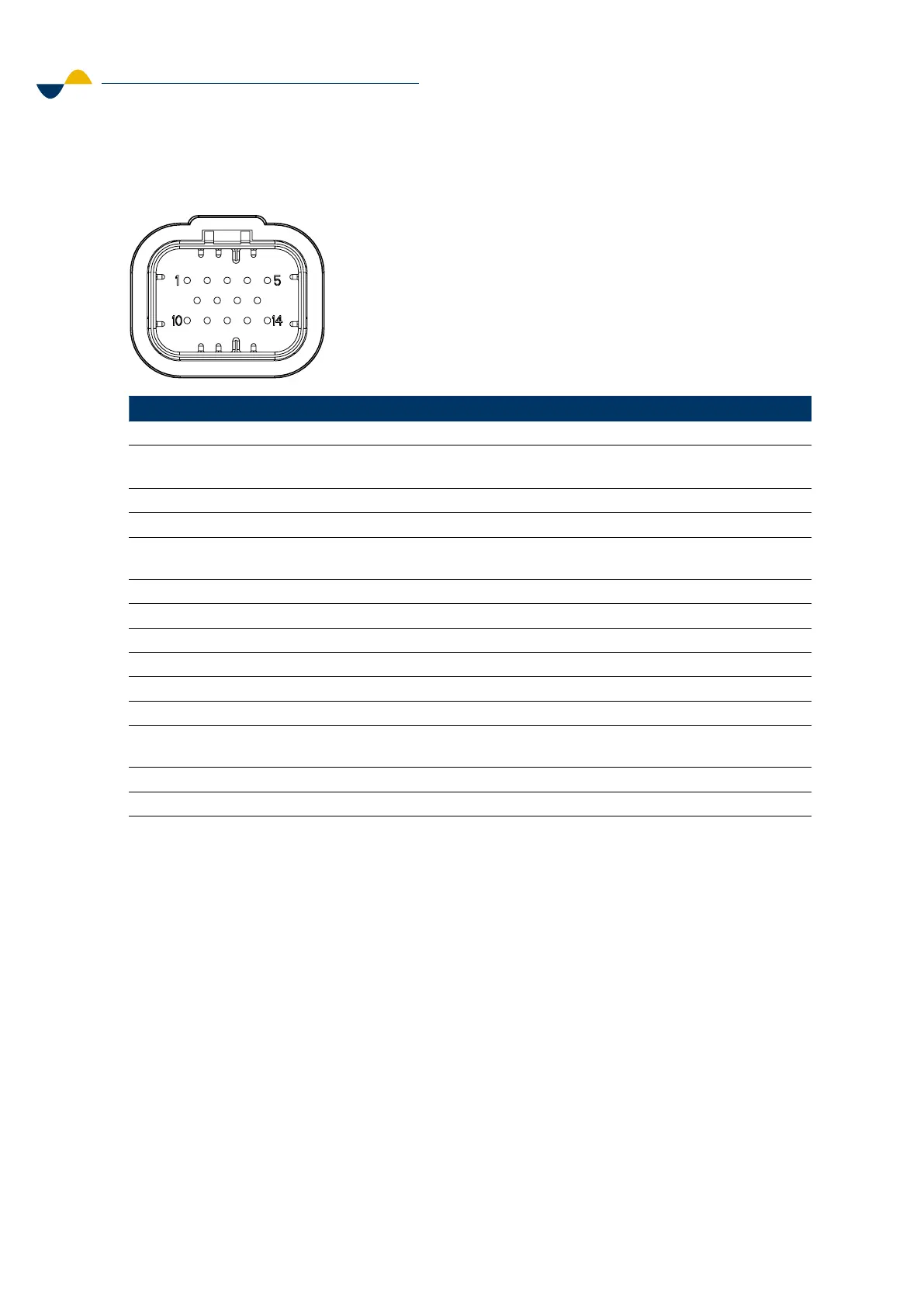
6.1.5. Receiver Pinout
Pin Signal Description
1 VIN REMOTE Power supply 12/24 VDC (Absolute maximum ratings 9-36 VDC) (Use external fuse 10 A)
2 LOOP IN Safety classified loop input 9-36 VDC. Closed when transmitter is switched on and
radio link established. Maximum load 6 A.
3 +CAB Supply voltage for transmitter tether control (optional).
4 GND Ground for transmitter tether control (optional).
5 LOOP OUT Safety classified loop output. Closed when transmitter is switched on and radio link
established. Maximum load 6 A.
6 GND Ground
7 CAN1_H CAN1 H
8 CABCAN_H Serial communication for tether control (optional).
9 CABCAN_L Serial communication for tether control (optional).
10 VIN MANUAL Input for enabling manual override
11 CAN1_L CAN1 L
12 ACT_MOV Temporarily high when safety analog actuators (e.g., joysticks, paddles, or safety
potentiometers) on the transmitter are activated. Maximum load 2 A.
13 GND Ground
14 STOP_OUT High when transmitter is switched on and radio link established Maximum load 2 A.
6.2. Receiver Installation
Make sure to follow the instructions in this chapter when installing the Receiver.
STEP 1: Find a good location on the machine and install the receiver.
1. Install the Receiver as high on the machine as possible or use an antenna extension
cable to get optimum radio communication.
2. Avoid screening or surrounding the antenna with fixed objects.
This will largely reduce the range of the radio signals.
3. Do not let the antenna touch any metal object.
14-Pin AMPSEAL
This document is our property. It must not be copied and its contents
must not be imparted to third persons without our written permission.
Infringement of the above will be prosecuted.
Där ej annat anges
Where not specified
Ritad av
Dwn By
Godk.
Appr.
Skala
Scale
Ersätter
Replacing
Filnamn
File Name
Ritn.nr/ Dwg. No.
Dat.
Date
Volym
Volume
Vikt
Weight
Dat.
Date
-
-
-
-
ISO 2768-m
-
-
1:1
-
-
SCANRECO
RADIO REMOTE CONTROL SYSTEM
RoHS compliant
 Loading...