– 37 –
Scanreco – Service Manual G6 Radio Remote Control System
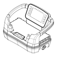
STEP 1: Connect the power cable.
1. Connect power cable to DC connector.
2. Place the power cable in the cable track to prevent it
from disconnecting.
3. The power supply of battery charger is made in three versions:
a. 12 / 24 VDC with 1,8 m / 5.9 ft cable for terminal supply
connection. Use a 3A external fuse.
b. 12 / 24 VDC with 1,8 m / 5.9 ft (extended length) coiled cable
with car adapter.
c. 110/230 VAC power supply with 1,5 m/4.11 ft power cable.
4. After installing the power supply cable in the Li-ion battery charger,
clamp the ferrite onto the cable 5 cm / 2 inches away from the
charger housing. Ferrite is included in the cardboard box with the
Li-ion charger. Ferrite does not apply for NiMH battery charger.
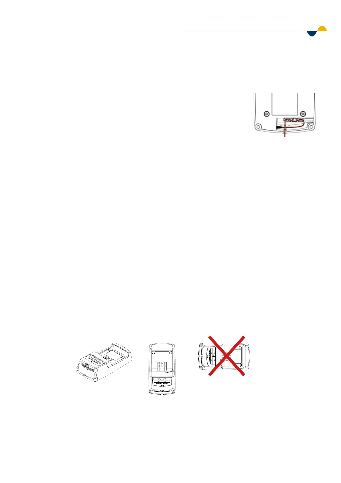
STEP 2: Mount the charger.
1. Mount the battery charger on a flat surface, preferably on a wall or
table. When mounting on a wall make sure to mount it vertically with
the power cable facing downwards.
2. Make sure to mount the charger at a height of maximum 2 meters
above the floor. This is to comply with the electrical safety standards.
3. Use four (4) M5 screws (one in each corner) when mounting
the charger.
a. Screw holes: Ø 4.4 mm / 0.17 inches.
b. Tighten the screws with a torque of 0.7 Nm.
Temp.
Ready
Charge
Fault
Power
Temp.
Ready
Charge
Fault
Power
Temp .
Ready
Charge
Fault
Power
Temp .
Ready
Charge
Fault
Power
6.5.2. Battery Charger Installation
 Loading...