Revision: 3.0 Page 42 of 70
from one board ... to the next
10.6. Bus wiring
Each bus node must be assigned a unique address within the bus.
Line topology
Line topology must be used for the bus wiring. Stubs should always be avoided.
Modbus:
The maximum stub length per burner control unit is 0.5 m
Wiring diagrams can be found in the document "SchwankControl Electrical Installations"
CAN bus:
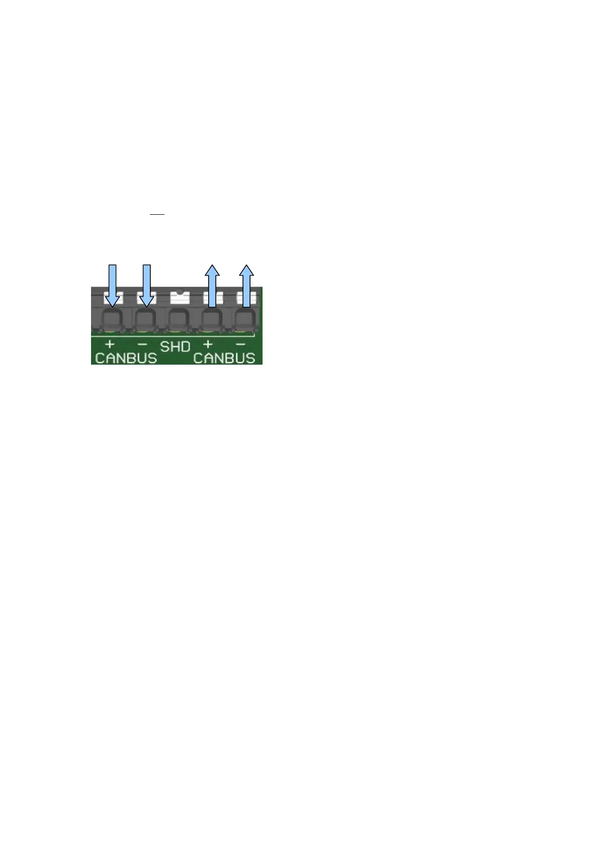
Stubs are not permissible. There are two clamping units per control unit for looping through the
bus [see illustration].
Clamping units must be either closed or connected!
The bus must either end at the clamping unit with a terminating resistor OR the wiring must lead to the
next node.
Bus termination
To terminate the buses, a 120 Ω terminating resistor between the data lines is required at both ends of
the bus wiring.
Modbus:
The control unit is equipped with a terminating resistor, i.e. the wiring must be carried out in such
a way that the line wiring ends at the control unit.
CAN bus:
The control unit is equipped with a terminating resistor, i.e. the wiring must be carried out in such
a way that the line wiring ends at the control unit.
If an operating unit is connected at both ends of the CAN bus, no additional terminating resistor
is required.
Figure 42: CAN-Bus control unit