7-46 Maintenance and Testing Date Code 20011026
SEL-321/321-1 Instruction Manual
Step 3. Connect the voltage sources to the A-phase, B-phase, and C-phase to neutral relay
voltage inputs. Connect the current source to the A-phase relay current input. Refer
to the voltage and current connections shown in Figure 7.6 as an example.
Step 4. Select the magnitude of the test signals, I
A
and V
A
.
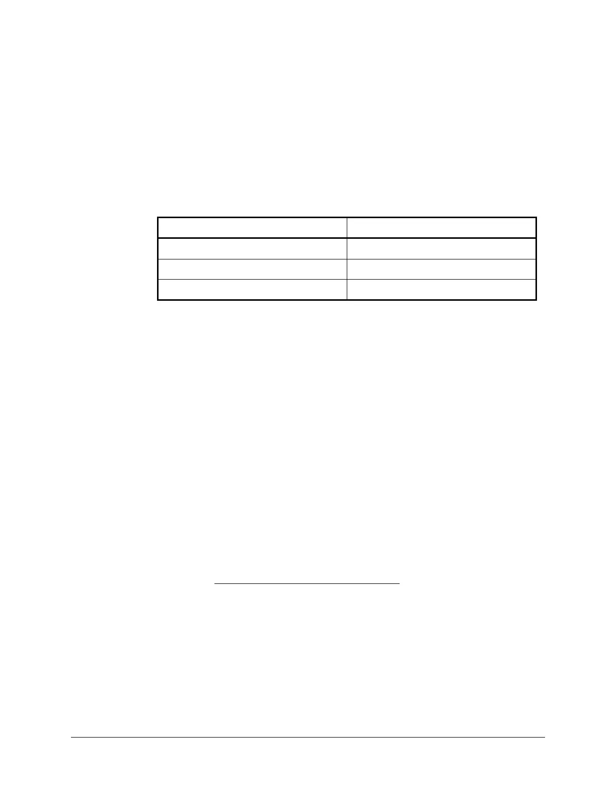
Table 7.5 summarizes the test quantities for the Zone 2 A-G ground quadrilateral
distance element based upon the example relay settings.
Table 7.5: Test Quantities for Zone 2 Ground Quadrilateral
Distance Element: Reactive Reach
Test Voltages Test Current
V
A
= 40.4 ∠0° volts I
TEST
= 2.49 ∠-90.0° amps
V
B
= 67.0 ∠-120° volts
V
C
= 67.0 ∠120° volts
The following text describes a hand calculation method you may use to calculate
relay distance element voltage and current test signals. If you do not wish to review
this information, go to Step 5.
The relay ground distance elements operate based upon the magnitude of applied
phase-ground impedance. The impedance calculation is supervised by the functions
described. To effectively test the distance elements, select test signals that fulfill the
impedance and supervisory requirements of the relay, but are within the ability of the
test sources to produce accurately.
The reactive reach of the quadrilateral distance element under test is defined by the
XG2 element setting. In this case XG2 = 9.36 secondary ohms. The impedance
measured by the relay for a ground fault is determined by the faulted phase voltage,
faulted phase current, and the residual current multiplied by the zero-sequence
current compensation factor, k0. The SEL-321 Relay uses k01M and k01A settings
to define the zero-sequence current compensation factor for Zone 1 ground distance
elements and the k0M and k0A settings to define that factor for the remaining zones.
The reactance measured by the relay ground quadrilateral distance element for a
Zone 2 fault is defined by the following equation:
()()
()()()
*T1II0kIANG1Z1Im
*T1IVIm
X
RRA
RA
AG
°∠⋅⋅+∠
°∠⋅
=
Equation 7.17
Where:
k0 = k0M ∠ k0A°
T = Non-homogenous system compensation setting
For a fault on a radial system and when testing a ground distance element using a
single current source, I
A
= I
R
. Equation 7.17 can be simplified: