7-50 Maintenance and Testing Date Code 20011026
SEL-321/321-1 Instruction Manual
ELOP setting prevents the Loss-of-Potential logic from blocking operation of the
relay distance elements if the test signals fulfill Loss-of-Potential conditions.
Step 2. Select an output contact to indicate operation of the Z2G element. In this example
use the OUT7 output.
From Access Level 2, execute the SET L n command to configure Output 7 to close
for assertion of the Z2G element.
=>>SET L 1 OUT7 <ENTER>
SET L 1 OUT7 <ENTER>SET L 1 OUT7 <ENTER>
SET L 1 OUT7 <ENTER>
SELogic group 1
OUT7 =NA
? Z2G
Z2GZ2G
Z2G <ENTER>
<ENTER><ENTER>
<ENTER>
OUT8 =32QR
? END <ENTER>
END <ENTER>END <ENTER>
END <ENTER>
After you type END <ENTER> to end the set procedure, the relay displays the
current logic settings. Type Y <ENTER> to accept those settings.
Connect output OUT7 to the sense input of your test set, an ohmmeter, or some other
contact sensing device.
Step 3. Connect the voltage sources to the A-phase, B-phase, and C-phase to neutral relay
voltage inputs. Connect the current source to the A-phase relay current input. Refer
to the voltage and current connections shown in Figure 7.6 as an example.
Step 4. Select the magnitude of the test signals, I
A
and V
A
.
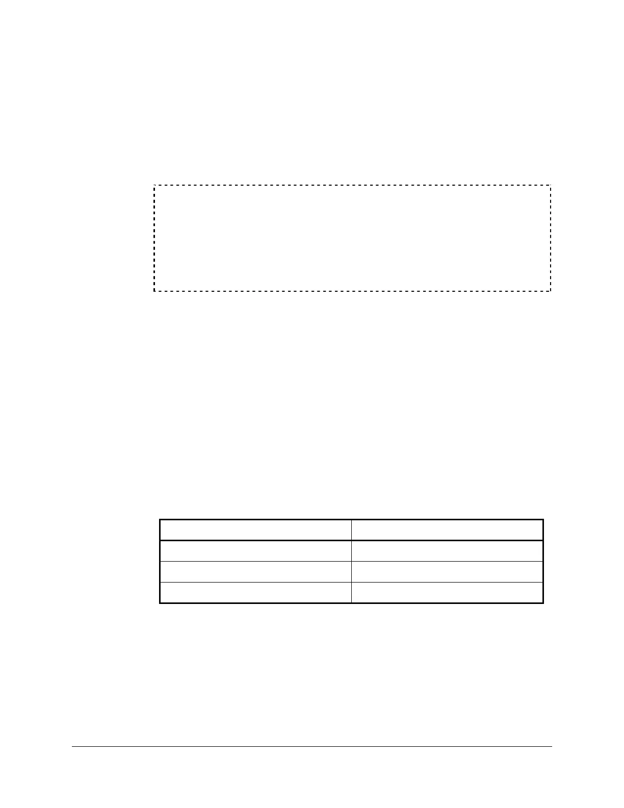
Table 7.6 summarizes the test quantities for the Zone 2 A-G ground quadrilateral
distance element based upon the example relay settings.
Table 7.6: Test Quantities for Zone 2 Ground Quadrilateral
Distance Element: Resistive Reach
Test Voltages Test Current
V
A
= 40.0 ∠0° volts I
TEST
= 8.0 ∠ 0.0° amps
V
B
= 67.0 ∠-120° volts
V
C
= 67.0 ∠120° volts
The following text describes a hand calculation method you may use to calculate
relay distance element voltage and current test signals. If you do not wish to review
this information, go to Step 5.
The relay ground distance elements operate based upon the magnitude of applied
phase-ground impedance. The impedance calculation is supervised by the functions
described. To effectively test the distance elements, select test signals that fulfill the
impedance and supervisory requirements of the relay, but are within the ability of the
test sources to produce accurately.