3-4
© 2014 SeaStar Solutions Optimus 360 Installation Supplement, Rev. B
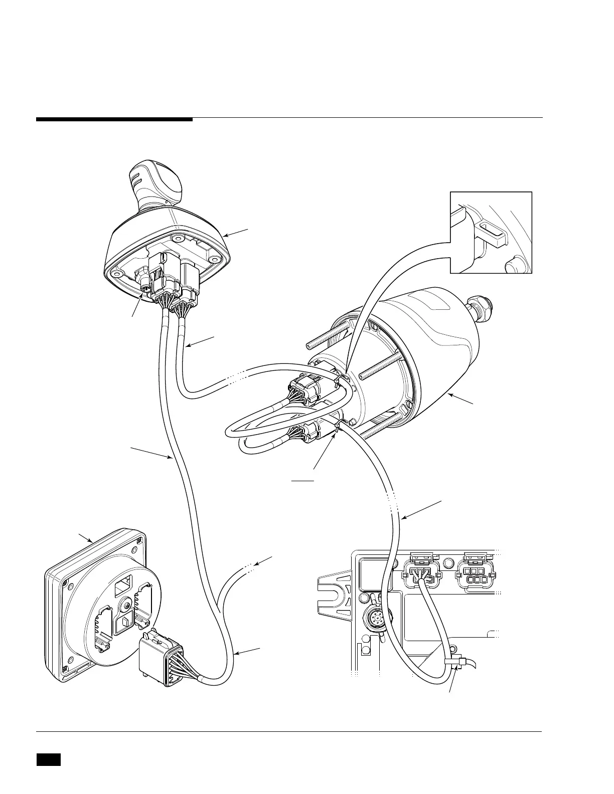
Figure 3-1 CAN1 harness connections.
CM21504
HARNESS
TO CAN2
NETWORK
NODE
CAN1 HARNESS TO
PCM P1 PORT
JOYSTICK
CAN2 PORT
(SEE SECTION 3.5)
HARNESSES MUST
BE STRAIN RELIEVED
TO JOYSTICK
MOUNTING STUD
USING CABLE TIES
PROVIDED
CANtrak
HARNESS TIE POINT X 4
HARNESS MUST BE
STRAIN RELIEVED TO HELM
HOUSING TAB USING
CABLE TIES PROVIDED
HARNESS MUST BE STRAIN RELIEVED TO
PCM STRAIN-RELIEF PLATE.
CAN1 HARNESS
TO HELM
ELECTRONIC
HELM
Refer to the Optimus EPS Installation Manual (Book 50) for CAN1
harness selection and connections.
In addition to this, the Optimus 360 system requires a 6-pin CAN1
harness connection between the steering helm and the joystick.
Refer to book 50 for proper harness selection
and strain relieving.
3.4 CAN1 Harness Connections
 Loading...

