8-1
© 2014 SeaStar Solutions Optimus 360 Installation Supplement, Rev. B
8.0 YANMAR
Install the control head on the dash in a location that allows
convenient and unobstructed access. Whenever possible, mount
the control head in a location that will minimize water spray.
Ensure that the control levers can be moved throughout their
complete range of motion in both forward and reverse without
interference. ABYC standard P-14 calls for a minimum of 2 1/2"
(64 mm) clearance between the control lever and the steering
wheel rim under all possible lever and wheel positions.
A dash cutout template is provided in Appendix A.
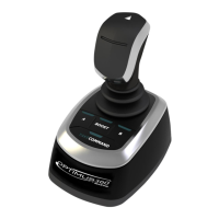
Control Head Trim Switch Connection
The control head includes a single trim/tilt switch on the end of the
port handle. This switch can be wired to provide synchronous trim/
tilt control of all engines. If independent trim/tilt is desired use tilt/
trim kit HA5491 (for twin engine configurations) and connect the
wiring as shown in figure 8-1.
8.1 Installing the Control Head
8.1.1
To complete the system installation for a Yanmar BY2/BY3 EST engine
with XT sterndrive
you need to:
1. Install the Optimus control head (section 8.1)
2. Complete the CAN network connections (section 8.2)
3. Set up the control head using Datalink (section 8.3)
 Loading...

