6-5
© 2014 SeaStar Solutions Optimus 360 Installation Supplement, Rev. B
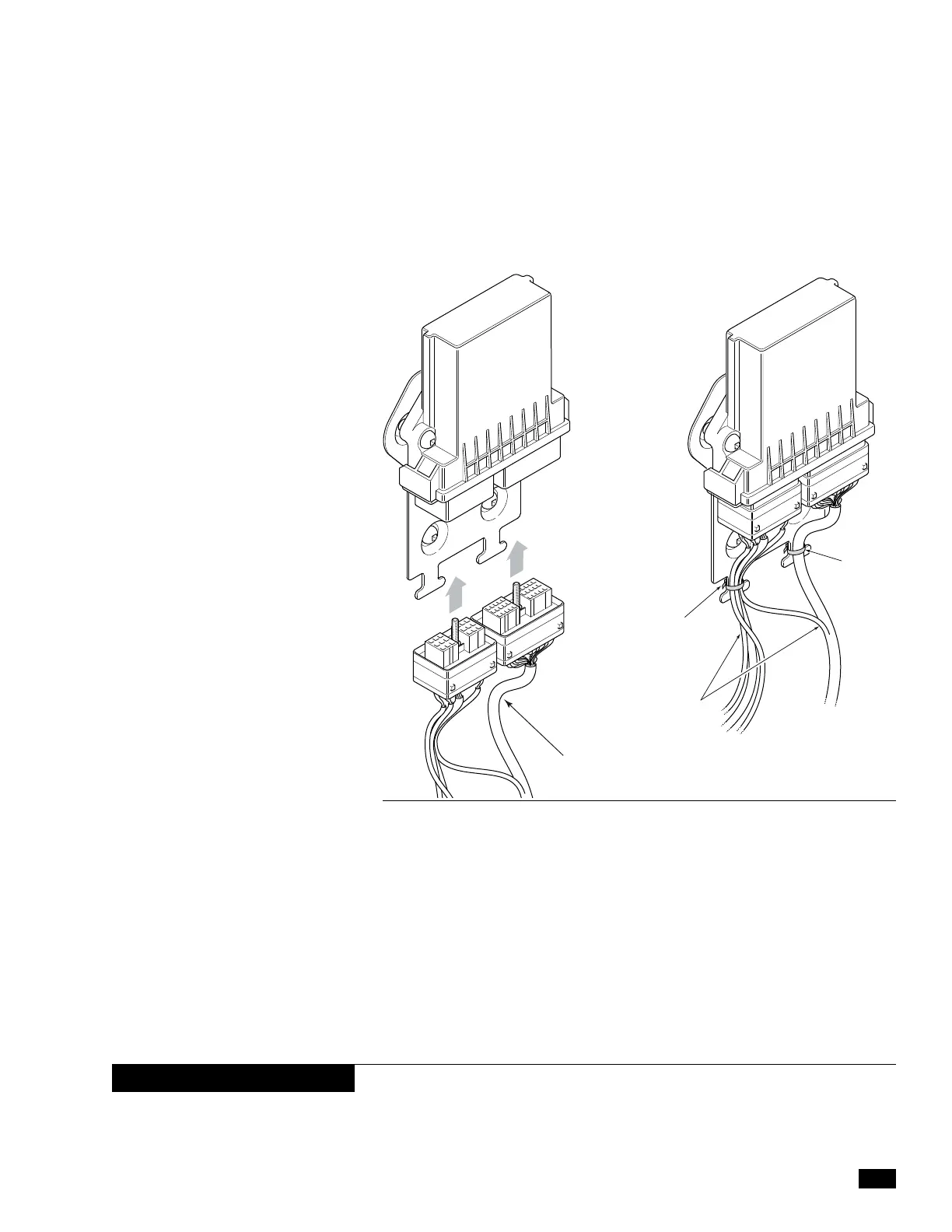
Figure 6-6. Harness connection to EST gateway.
Optimus EST Gateway Connection
Connect the two large connectors on the CM20018 harness to the
gateway and tighten the screws to secure them. Use cable ties to secure
the harness cables to the strain relief plate as shown in figure 6-6.
Optimus CAN1 and CAN2 Connections
The CM20018 harness has a CAN1 and a CAN2 connector. Connect
these to the networks as shown in section 3. To make the CAN1 con-
n
ection you may require the CM21702 wye harness shown in figure
6-2 and figure 6-3. The wye harness converts one CAN1 port into two.
CM20018
HARNESS
CABLE TIE
GATEWAY HARNESS
PART NO. CM20018
CABLE TIE
6.2.3
6.2.4
Optimus PCM Ignition Sensing
There are two purple ignition sensing wires on the PCM harness
CM20304. You need to connect both these wires to ensure that damage
to one ignition wire does not cause the steering to shut down.
If you are retrofitting an existing EPS installation these ignition
sensing wires will have already been connected to the ignition key
switch. Remove these connections and make the connections
outlined below.
6.2.5
NOTICE
 Loading...

