6-2
© 2014 SeaStar Solutions Optimus 360 Installation Supplement, Rev. B
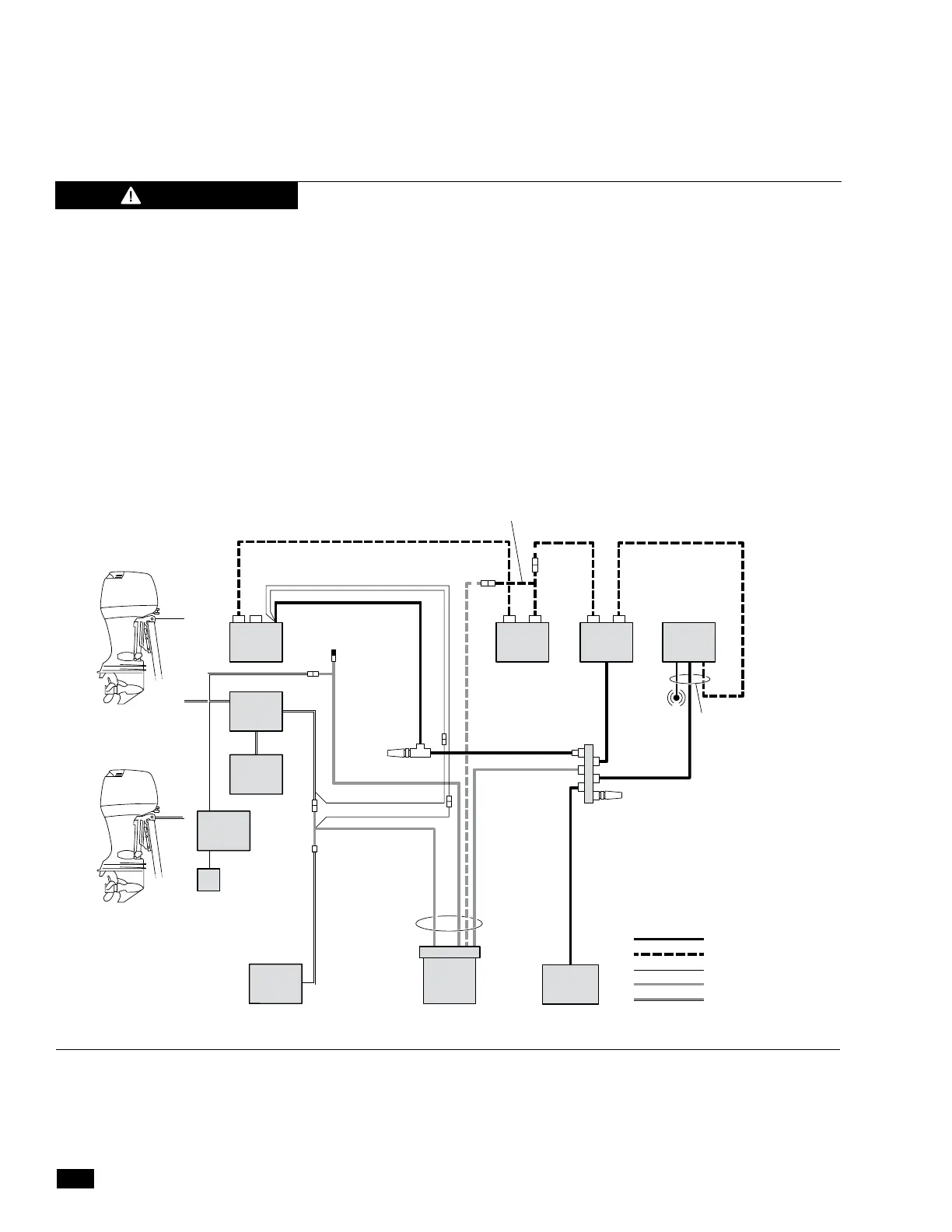
6.2 Suzuki EST Gateway and Optimus 360
Interconnection
The Suzuki Precision Control (SPC) shift and throttle system connects
to the Optimus 360 system through the EST Gateway, using the harness
CM20018. The harness connects at the following points:
Figure 6-2. Suzuki EST single station, twin engine.
1. Suzuki boat control module (BCM) CAN network connector
2. Suzuki switch panel harness
3. Optimus EST gateway
4. Optimus CAN1 & CAN2 networks
5. Optimus PCM ignition sensing
Figure 6-2 and figure 6-3 show the network interconnections in
schematic form.
COLOR
CANtrak 1
JOYSTICK
1
HELM
1
CERTIFIED
AUTOPILOT
(Optional)
PCM
PORT
ENGINE
STBD
ENGINE
OPTIMUS CAN2
OPTIMUS CAN1
IGNITION
CM20018
EXISTING SUZUKI
HARNESS
EST
GATEWAY
EG1810
CM204XX
CM204XX
CM21702
CM21504
CM20064
CM20018
CM20304
CM100XX
CM100XX
PURPLE x 2
PURPLE x 1
GRAY x 1
TERMINATOR
CM10051
TEE
CM10060
SUZUKI DBW
TERMINATOR
BUZZER
TERMINATOR
CM10052
SUZUKI DIAGNOSTIC
SOFTWARE PLUG IN
POINT
MAIN
BCM
CONTROL
HEAD 1
SUZUKI
SWITCH
PANEL
IGNITION
SWITCH
All harness runs should be sufficiently
bundled and strain relieved to
avoid wear or accidental damage.
CAUTION
 Loading...

