3-5
© 2014 SeaStar Solutions Optimus 360 Installation Supplement, Rev. B
The Optimus 360 system uses the same CAN2 network, cables and
structure as the basic Optimus EPS system. T
he Optimus 360 system
adds a joystick and control head (if applicable)
to the CAN2 network.
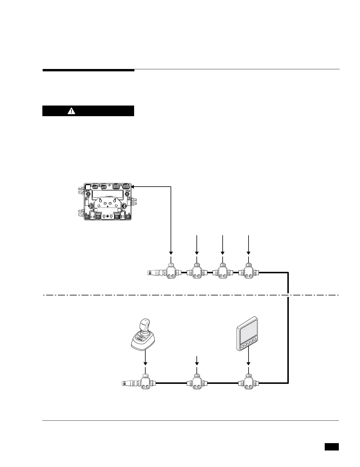
Figure 3-2 shows a sample CAN2 network diagram. The exact
connections will vary depending on the engine manufacturer; consult
the OEM-specific sections of this manual for detailed network diagrams.
Refer also to Book 50 for CAN2 wiring, harness selection, and
installation best practices.
All tees must be secured using both screw holes, and the cable
drops
at each tee must be appropriately secured and strain-relieved to prevent
any pull on the tees. See figure 3-3 for proper tee installation. Any
unused tees must either be capped or removed.
3.5 CAN2 Harness Connections
Figure 3-2. Generic CAN2 wiring diagram.
NETWORK TEES CM10060 OR
SIX-PORT HUB CM20064
NETWORK TEES CM10060 OR
SIX-PORT HUB CM20064
* See Book 50 Optimus EPS Installation Manual
DEVICENET
HARNESS*
DEVICENET HARNESS*
4'
HARNESS
CM21504
4' HARNESS CM20304
POSSIBLE EST NETWORK
CONNECTION POINT
OPTIONAL AUTOPILOT
CONTROLLER
POSSIBLE EST NETWORK
CONNECTION POINT
DATALINK
CONNECTION POINT
MALE
TERMINATOR
CM10051
FEMALE
TERMINATOR
CM10052
PCM
JOYSTICK
COLOR
CANtrak
HATCH OR CONSOLE
MOUNTED COMPONENTS
OPTIMUS 360 DASH
MOUNTED COMPONENTS
FAILURE TO SECURE HARNESS
MAY RESULT IN HARNESS
WEAR, CAUSING LOSS OF
STEERING CONTROL, PROPERTY
DAMAGE, PERSONAL INJURY
AND/OR DEATH.
WARNING
 Loading...

