5-2
© 2014 SeaStar Solutions Optimus 360 Installation Supplement, Rev. B
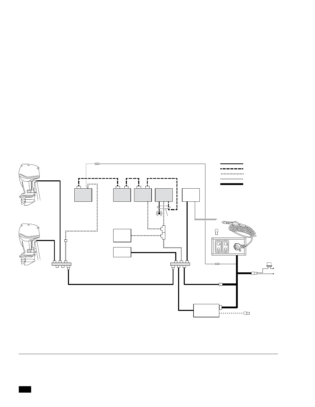
Figure 5-1. Evinrude ICON-CAN2 interconnection, single station, twin engine.
RUN
OFF
COLOR
CANtrak 1
EST GATEWAY
(by EVINRUDE)
JOYSTICK 1HELM 1PCM
PORT
ENGINE
STBD
ENGINE
CM20304
CM20406CM204XX
CM20016
CM20016
CM20021
IGNITION
TO ENGINE
BATTERY
(use Evinrude
harness
764921)
TO NMEA 2000
PUBLIC NETWORK
EXTENSION
CABLE (if Req.)
See ICON guide
FUSE
PURPLE
PURPLE
+
–
EVINRUDE EST-CAN
OPTIMUS CAN1
OPTIMUS CAN2
CM20016 ADAPTER
CM20021 ADAPTER
CH TO KEY SWITCH
CONTROL
HEAD 1
CERTIFIED
AUTOPILOT
(OPTIONAL)
ACC RELAY
(EVINRUDE)
CM21504
BUZZER
ICON HUB WITH
INTERNAL
TERMINATION
(764943
ICON HUB WITH
INTERNAL
TERMINATION
(764943
Use crimped Molex Perma-Seal (or equivalent) butt splice connectors,
or shrink-sealed solder connections. Locate all splices in a dry location
and secure them properly against mechanical damage.
Supplied with the Evinrude system is an accessory relay that provides
power to the CAN network when the key switch is in the accessory
position. It normally plugs into the ICON hub but in some cases you
will need to remove it to connect the CAN2 network. In this case
you will need to buy the adapter harness CM20017 to connect the
relay to an Optimus network tee.
Figure 5-1 and 5-2 illustrate the network interconnection for single
and dual station applications. All adapter harnesses are identified
in the figures.
Note: Aft-mounted PCM shown. If PCM is mounted forward you can
connect CM20304 directly to a CAN2 tee.
 Loading...

