7-2
© 2014 SeaStar Solutions Optimus 360 Installation Supplement, Rev. B
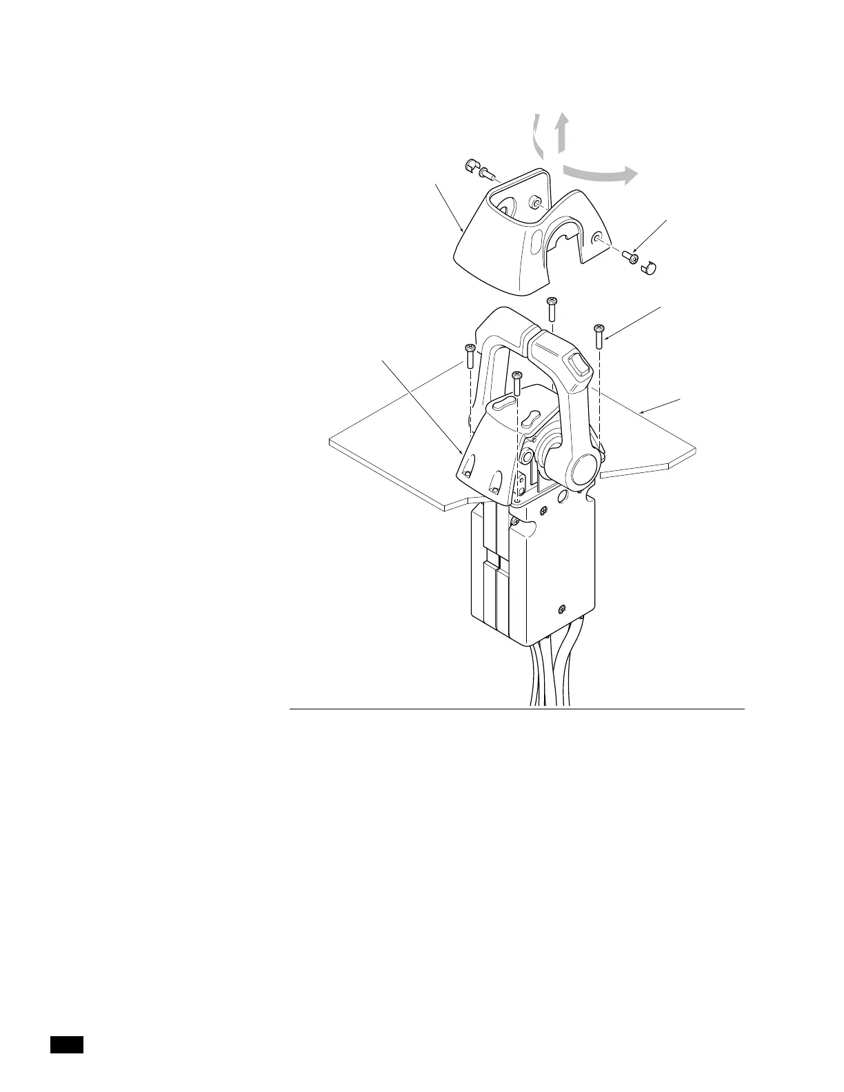
Figure 7-1. Control Head Binnacle removal.
DASH
SCREW x 2
BINNACLE COVER
CONTROL HEAD
BINNACLE
SCREW x 4
4. Remove the control head from the dash far enough to expose the
cover mounting screws. (Refer to figure 7-2. Port side is shown.)
Both sides will need to be removed, but it is recommended that
you proceed with one side at a time. Be sure to support the
control head so that the harnesses are not under strain.
5. Cut the cable tie securing the harnesses to the binnacle
chassis. (Refer to figure 7-2.)
6. Disconnect the Yamaha LPS harness. The port harness will be
identified with a ‘P’ and the starboard harness will be identified
with an ‘S’. (Refer to figure 7-2.) If this is a triple, do not connect
to the harnesses labeled 'PC' or 'SC'.
7. Connect the SeaStar gateway harness as shown in figure 7-3.
Port harness is identified ‘P_LPS’ and the starboard harness is
identified ‘S_LPS.’
 Loading...

