4.49
Date Code 20080103 Instruction Manual SEL-351S Relay
Loss-of-Potential, Load Encroachment, and Directional Element Logic
Directional Control Settings
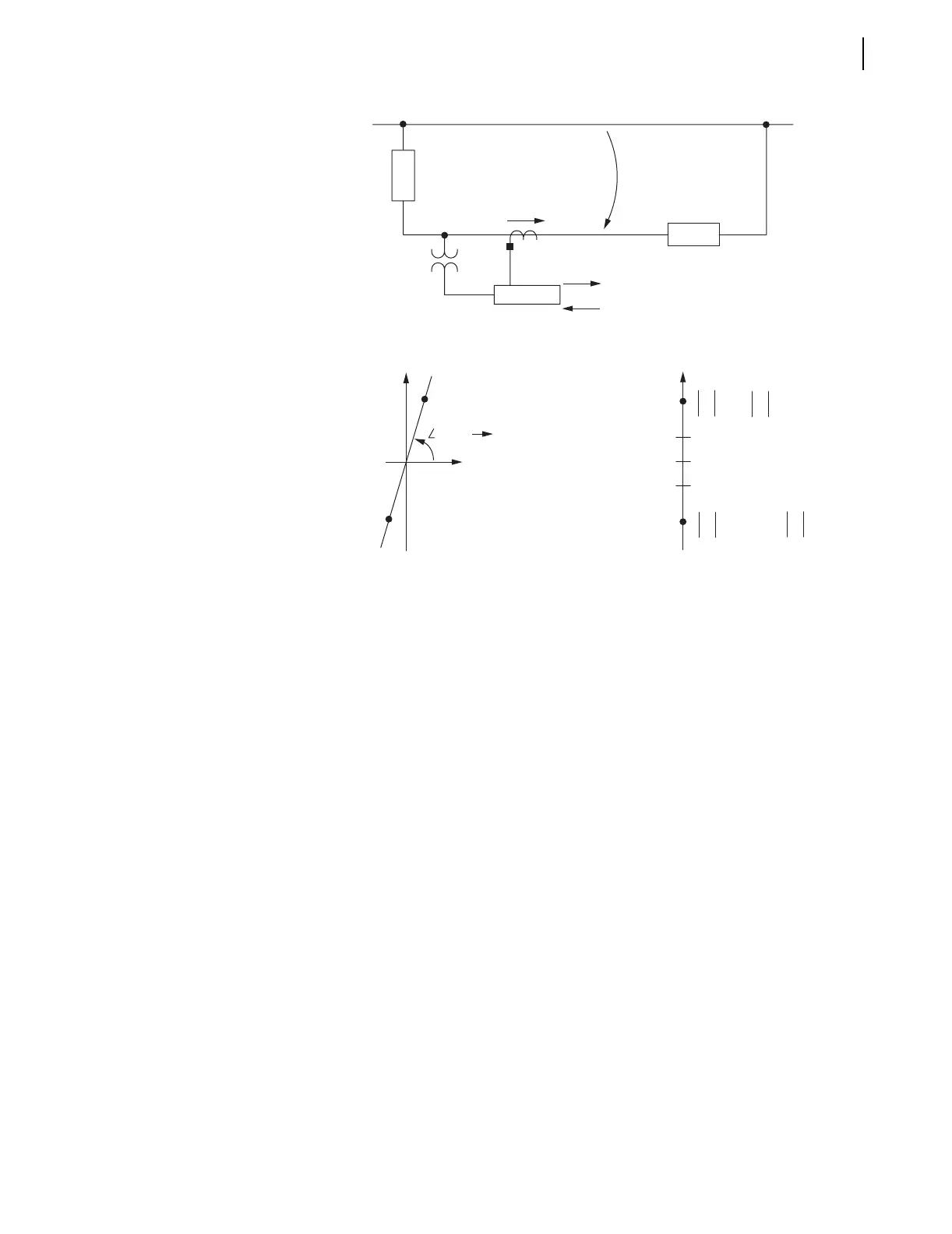
Figure 4.25 Zero-Sequence Impedance Network and Relay Polarity
Figure 4.26 Zero-Sequence Impedance Plot for Solidly-Grounded, Mostly
Inductive System
Z0MTA—Zero-Sequence Maximum Torque Angle
Setting Range:
–90.00 to –5.00 degrees
5.00 to 90.00 degrees
If enable setting E32 = Y and ORDER contains a V or S, setting Z0MTA
should be set. Z0MTA must be set to compensate for the neutral ground
resistor and is used in the Best Choice Ground Directional Logic
™
to make
proper forward and reverse fault determination (see Figure 9.22).
If enable setting E32 = AUTO, then Z0MTA is set equal to Z0ANG and
Z0MTA is hidden.
50NFP—Forward Directional Neutral Ground Current Pickup
50NRP—Reverse Directional Neutral Ground Current Pickup
Setting Range:
0.005–5.00 A secondary (0.2 A nominal neutral channel input, IN)
If preceding setting ORDER does not contain S or U (zero-sequence voltage-
polarized directional elements: low-impedance or ungrounded/high-
impedance grounded, are not enabled) or the model does not have a 0.2 A
nominal neutral channel (IN), then settings 50NFP and 50NRP are not made or
displayed.
I
0
V
0
Z
N
Z
M
Forward
Reverse
Zero-Sequence Reference Bus
SEL-351
(a) Impedance Plot (b) Z0F and Z0R Settings
Z
N
= R
N
+ jX
N
(Reverse)
–Z
M
= —R
M
— jX
M
(Forward)
R
jX
Reverse
Forward
Z0F
Z
0
Z0R
Z
N
— Z
M
Z
N
> Z0R
Z0F > — Z
M
Z0R > Z0F
Zero-Sequence
Maximum Torque Angle
Z0MTA

 Loading...


