5.29
Date Code 20080103 Instruction Manual SEL-351S Relay
Trip and Target Logic
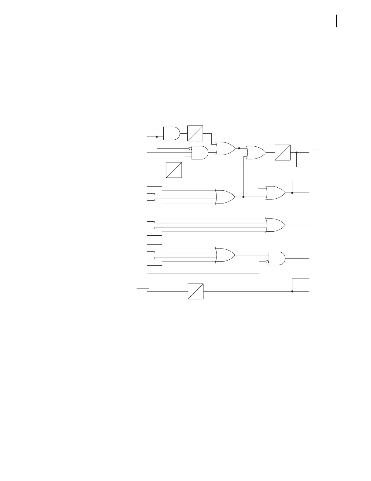
Directional Comparison Blocking (DCB) Logic
In a three-terminal line scheme, output contact OUT208 is set the same as
OUT106 (see Figure 5.16):
OUT208 = STOP
BTX—Block Trip Extension
The received block trip input (e.g., BT = IN104) is routed through a dropout
timer (BTXD) in the DCB logic in Figure 5.14. The timer output (BTX) is
routed to the trip logic in Figure 5.1.
q Figure 5.1.
Figure 5.14 DCB Logic
Installation
Variations
Figure 5.16 shows output contacts OUT105, OUT106, OUT107, and OUT208
connected to separate communication equipment, for the two remote
terminals. Both output contact pairs are programmed the same
(OUT105 = DSTRT + NSTRT and OUT107 = DSTRT + NSTRT;
OUT106 = STOP and OUT208 = STOP).
Depending on the installation, perhaps one output contact (e.g.,
OUT105 = DSTRT + NSTRT) can be connected in parallel to both START
inputs on the communication equipment in Figure 5.16. Then output contact
OUT107 can be used for another function.
Depending on the installation, perhaps one output contact (e.g.,
OUT106 = STOP) can be connected in parallel to both STOP inputs on the
communication equipment in Figure 5.16. Then output contact OUT208 can be
used for another function.
67Q3
67G3
67N3
67P3
50Q3
50G3
50N3
50P3
67Q2S
67G2S
67N2S
67P2S
DSTRT
BT
50P3
VPOLV
67P3
to Trip
Logic q
to Trip
Logic q
Z3XT
DSTRT
NSTRT
STOP
BTX
Directional
Start
Nondirectional
Start
0
1/4
CYC
0
BTXD
Z3XPU
Z3XD
2
CYC
0
Relay
Word
Bits
Relay
Word
Bits
SELOGIC
Setting