11.16
SEL-351S Relay Instruction Manual Date Code 20080103
Front-Panel Interface
Operator Controls
Operator Controls
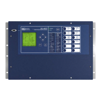
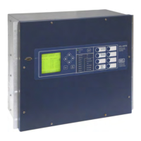
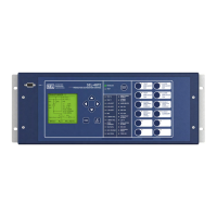
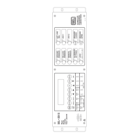
Refer to Figure 1.2, Figure 2.2, Figure 2.3, Figure 2.4, Figure 2.5, and
Figure 2.6 for the layout of the front-panel operator controls. Except for the
{LOCK} operator control pushbutton, all the following operator control
pushbuttons should be pressed momentarily to execute their function.
NOTE: The functions described in
Table 11.1 are based on the factory
default settings and operator control
labels.
NOTE: On some models, the
operator-control labels can be user-
configured. See User-Configurable
Label Option for the Front Panel on
page 2.9.
Table 11.1 SEL-351S Front-Panel Operator Control Functions (Sheet 1 of 3)
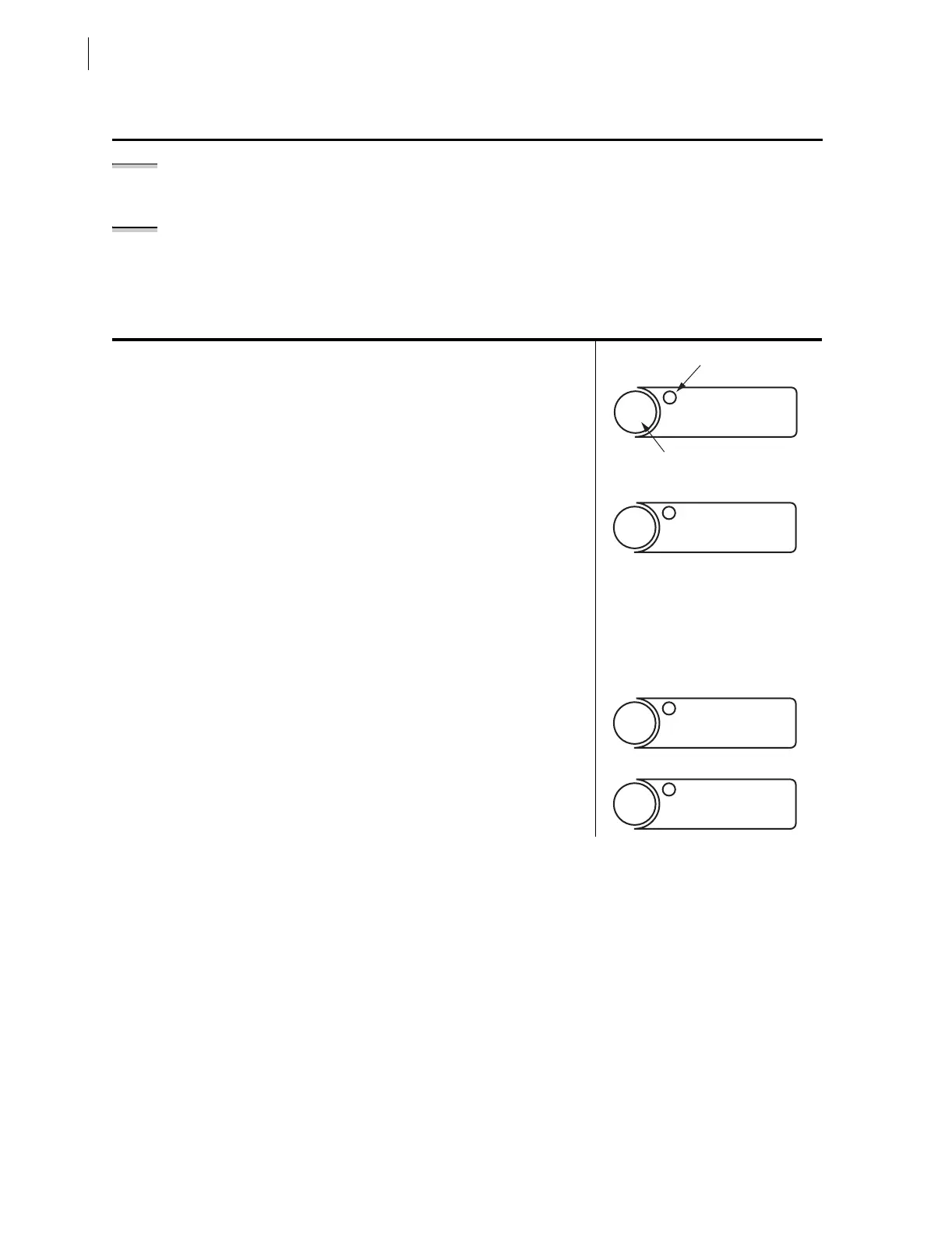
Press the {GROUND ENABLED} operator control pushbutton to enable/disable ground over-
current element tripping. Corresponding LED illuminates to indicate the enabled state.
See the discussion surrounding Figure 11.4 on making ground overcurrent element
torque control settings changes to allow the {GROUND ENABLED} operator control to enable/
disable newly set ground overcurrent elements.
Press the {RECLOSE ENABLED} operator control pushbutton to enable/disable auto reclosing.
Corresponding LED illuminates to indicate the enabled state.
The {RECLOSE ENABLED} operator control is overridden by the operation of the
{HOT LINE TAG} operator control in the following scenario:
Initial state: {RECLOSE ENABLED} “on” or “off” and {HOT LINE TAG} “off.”
Action: Press {HOT LINE TAG} operator control pushbutton.
Result: {RECLOSE ENABLED} “off” and {HOT LINE TAG} “on.” The {RECLOSE ENABLED}
operator control is now nonfunctional (remains “off”).
{RECLOSE ENABLED} cannot be turned “on” again, until {HOT LINE TAG} is turned “off.” Once
{HOT LINE TAG} is “off,” the {RECLOSE ENABLED} operator control is then functional, but
remains “off” until the {RECLOSE ENABLED} operator control pushbutton is pressed again.
Press the {REMOTE ENABLED} operator control pushbutton to enable/disable remote control.
Corresponding LED illuminates to indicate the enabled state.
NOTE: The {REMOTE ENABLED} operator control is not operable with the factory set-
tings. See Figure 11.17 for information and ideas on how to program this control.
Press the {ALTERNATE SETTINGS} operator control pushbutton to switch the active setting
group between the main setting group (Setting Group 1) and the alternate setting group
(Setting Group 2). Corresponding LED illuminates to indicate that the alternate setting
group is active.
GROUND
ENABLED
LED
Operator Control
Pushbutton
RECLOSE
ENABLED
REMOTE
ENABLED
ALTERNATE
SETTINGS


 To Next Page