2.44
SEL-351S Relay Instruction Manual Date Code 20080103
Installation
Circuit Board Connections
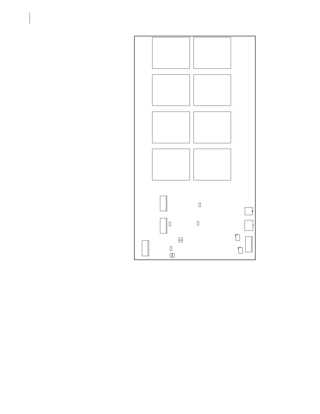
Figure 2.35 Jumper Locations for the 0351Sxxx5/6/A/B Model Magnetics/
Auxiliary Pushbutton Board
Output Contact
Jumpers
Table 2.3 shows the correspondence between output contact jumpers and the
output contacts they control. The referenced figures show the exact location
and correspondence. With a jumper in the A position, the corresponding
output contact is an “a” type output contact. An “a” type output contact is
open when the output contact coil is de-energized and closed when the output
contact coil is energized. With a jumper in the B position, the corresponding
output contact is a “b” type output contact. A “b” type output contact is closed
when the output contact coil is de-energized and open when the output contact
coil is energized. These jumpers are soldered in place.
In the figures referenced in Tab le 2.3, note that the ALARM output contacts are
“b” type output contacts and the other output contacts are all “a” type output
contacts. This is how these jumpers are configured in a standard relay
shipment. Refer to corresponding Figure 7.27–Figure 7.28 for examples of
output contact operation for different output contact types.
J18
J19
JMP4JMP1
JMP7
JMP2
JMP6
JMP5
JMP3
JMP8



 To Next Page