G.8
SEL-351S Relay Instruction Manual Date Code 20080103
Setting SELOGIC Control Equations
SEL
OGIC Control Equations
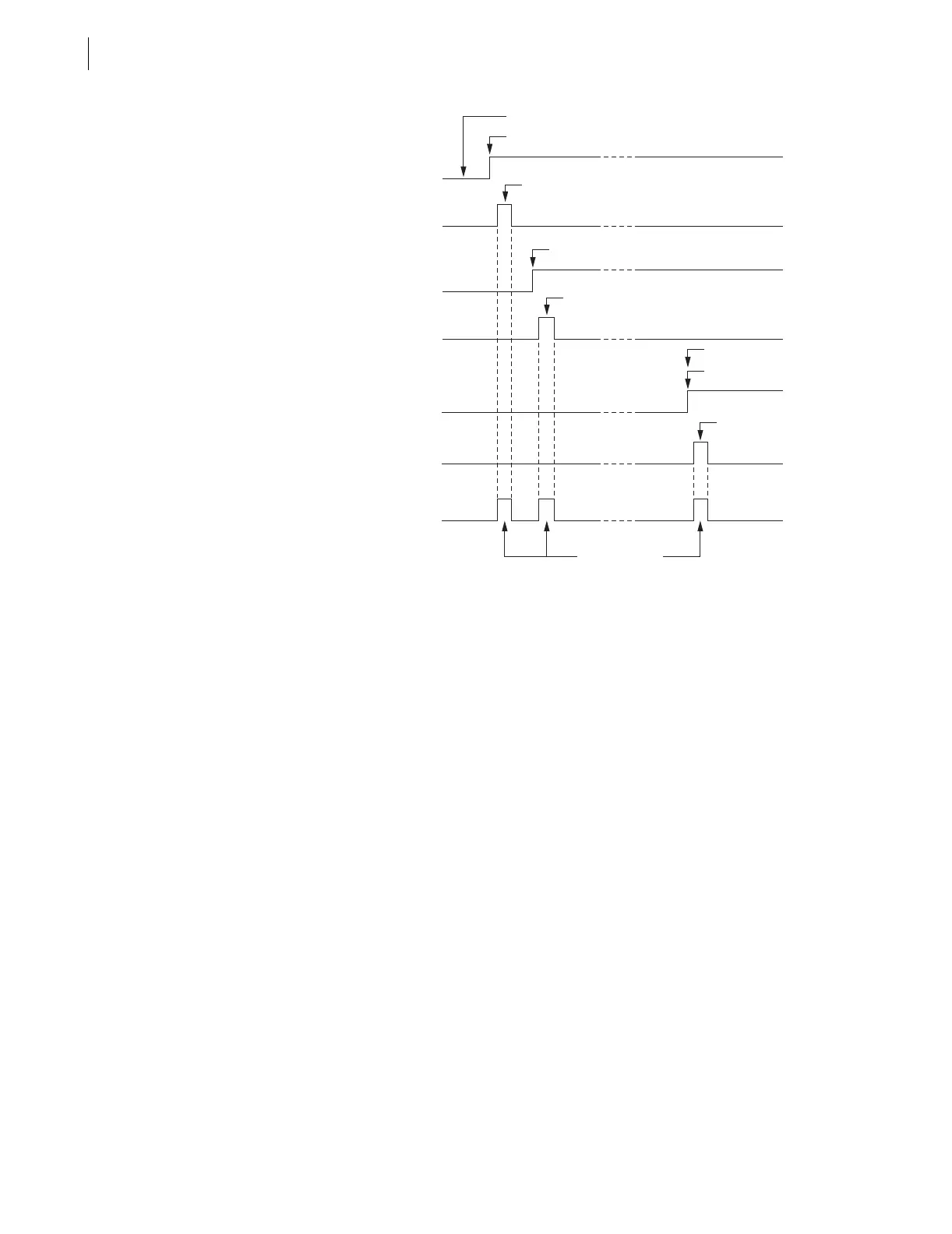
Figure G.1 Result of Rising Edge Operators on Individual Elements in
Setting ER
Note in Figure G.1 that setting ER sees three separate rising edges, due to the
application of rising edge operators /. The rising edge operator / in front of a
Relay Word bit sees this logical 0 to logical 1 transition as a “rising edge” and
the resultant asserts to logical 1 for one processing interval. The assertions of
51G1 and 51P1 are close enough that they will be on the same event report
(generated by 51G1 asserting first). The assertion of OUT103 for a breaker
failure condition is some appreciable time later and will generate another
event report, if the first event report capture has ended when OUT103 asserts.
If the rising edge operators / were not applied and setting ER was
ER = 51P1 + 51G1 + OUT103
the ER setting would not see the assertion of OUT103, because 51G1 and
51P1 would continue to be asserted at logical 1, as shown in Table G.3.
SELOGIC Control Equation Falling Edge Operator \
The falling edge operator \ is applied to individual Relay Word bits only—not
to groups of elements within parentheses. The falling edge operator \ operates
similar to the rising edge operator, but looks for Relay Word bit deassertion
(element going from logical 1 to logical 0). The falling edge operator \ in front
of a Relay Word bit sees this logical 1 to logical 0 transition as a “falling
edge” and asserts to logical 1 for one processing interval.
For example, suppose the SEL
OGIC control equation event report generation
setting is set with the detection of the falling edge of an underfrequency
element:
ER = ... + \81D1T
Rising Edge Operator Output
ER = /51P1 + /51G1
+ /OUT103
/51P1
Rising Edge
51P1
Rising Edge Operator Output
/51G1
Rising Edge
Ground Fault Inception
51G1
/OUT103
Rising Edge
Operator Output
OUT103
Rising Edge
Breaker Failure Trip
Each Pulse is
One Processing
Interval Width


 To Next Page