5.33
Date Code 20080103 Instruction Manual SEL-351S Relay
Trip and Target Logic
Front-Panel Target LEDs
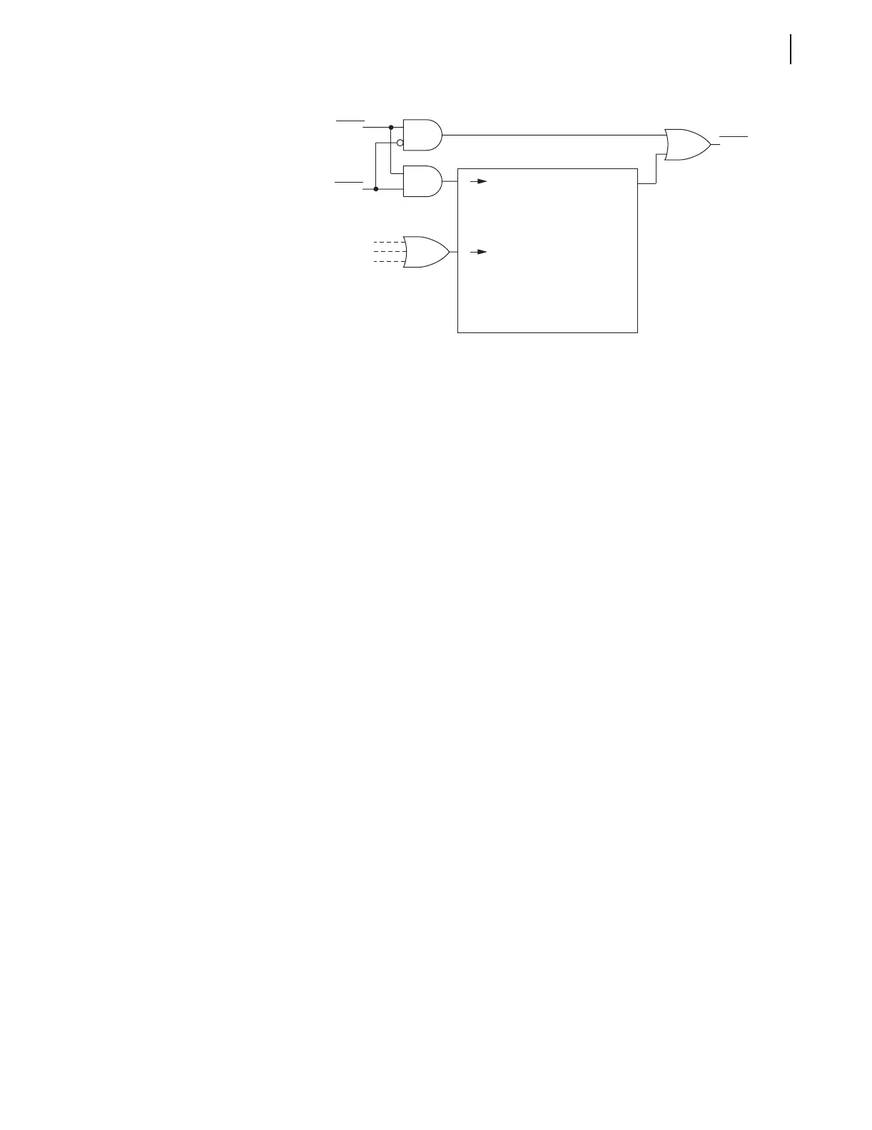
Figure 5.17 Programmable Front-Panel Target LED Logic
Front-Panel Target
LED Logic Details
Refer to Table 5.1 and Figure 5.17.
LED12–LED21 (TRIP–LOCKOUT), LED25 (G), and LED26 (N) are programmable via
the SEL
OGIC control equation settings and global settings shown in Tab le 5.1.
They either latch in on the rising-edge of trip (new assertion of Relay Word bit
TRIP—see logic output of Figure 5.1) or follow the state of the corresponding
SEL
OGIC control equation setting (illuminated = logical 1; extinguished =
logical 0).
LED11 (ENABLED) and LED22–LED24 (A, B, and C) do not have settings—they are
fixed-function LEDs.
LEDs A, B, and C always latch in on trip, if the corresponding phase is involved
with the fault. LEDs A, B, and C reset (unlatch) similar to the other target LEDs
set to latch in on trip. SEL
OGIC control equation FAULT has to be picked up
for three-phase fault indication (FAULT = 51P1 + 51G1 in the factory default
settings—set with the pickup indicators of the time-overcurrent elements).
Additionally, the fault must be present for at least one cycle after the relay
trips for reliable targeting. This is most noticeable in relay testing when
breaker opening times are not included in the test setup.
SEL
OGIC control equation setting FAULT also controls other relay functions.
See subsection SEL
OGIC Control Equation Setting FAULT on page 5.37.
If neutral channel IN is rated 0.2 A nominal and directional control is selected
for a Petersen Coil grounded or ungrounded/high-impedance grounded system
(see Table 4.3), then A, B, and C target logic for ground faults uses Relay
Word bits NSA, NSB, and NSC in determining the involved phase for forward
faults only.
The LED logic output (TLED11–TLED26) that actually drives the front-panel
LEDs is observed via the TAR 0 and TAR 1 commands (see Table 10.6).
TLED19–TLED26 (RESET–N) are available as Relay Word bits (see Tabl e 9.6,
row 51—note the “T” is dropped from the front, so they are listed as LED19–
LED26 in row 51). Use Relay Word bits LED22–LED25 (A, B, C, and G) to
indicate the type of fault to particular SCADA systems (those requiring an
output contact interface; e.g., set OUT103 = LED22, OUT104 = LED23, …).
S
Q
new TRIP
breaker closes (global
setting RSTLED = Y
Target Reset Pushbutton
or command (TAR R)
R Reset (unlatch) if any
of the following occur:
LEDx
LEDxL
(Latch in on trip?
Y = logical 1, N = logical 0)
Set (latch in) on rising
edge of TRIP
Latched
TLEDx
Follow state of SEL
OGIC setting
Set/Reset Latch
x = 12 through 21, 25, and 26
SELOGIC
Setting
Global
Setting
LED
Output
•
•
•



 To Next Page