2.47
Date Code 20080103 Instruction Manual SEL-351S Relay
Installation
Circuit Board Connections
Condition of Acceptability for North American Product Safety
Compliance
To meet product safety compliance for end-use applications in North America,
use an external fused rated 3 A or less in-line with the +5 Vdc source on Pin 1.
SEL fiber-optic transceivers include a fuse that meets this requirement.
Auxiliary {TRIP}/
{CLOSE} Pushbutton
and Breaker Status
LED Jumpers
(0351Sxxx5/6/A/B
models only)
The jumpers listed in Table 2.9 are used to select the proper control voltage for
breaker open/closed indicating LEDs on the front panel of the relay.
Figure 2.35 shows the jumper locations on the magnetics/auxiliary pushbutton
board. The jumpers come preset from the factory with the voltage range set
the same as the control input voltage, as determined by the part number at
order time.
The voltage setting can be different for each LED. To access these jumpers,
the relay front cover, top cover, main board, and any additional I/O board (if
present) must first be removed. See instructions and precautions in the
subsection Accessing the Relay Circuit Boards on page 2.40.
Table 2.10 shows how to enable or disable the arc suppression feature of the
{TRIP} and {CLOSE} pushbuttons. If ac control power is used to operate the
breaker, then the corresponding arc suppression jumper must be removed. If
dc control power is used to operate the breaker, then the arc suppression is
strongly recommended to break inductive loads. The arc suppression comes
enabled from the factory. Figure 2.35 shows the jumper locations on the
magnetics/auxiliary pushbutton board.
Clock Battery
Refer to Figure 2.32 for clock battery location (front of main board). A
lithium battery powers the relay clock (date and time) if the external dc source
is lost or removed. The battery is a 3 V lithium coin cell. At room temperature
(25ºC), the battery will nominally operate for 10 years at rated load.
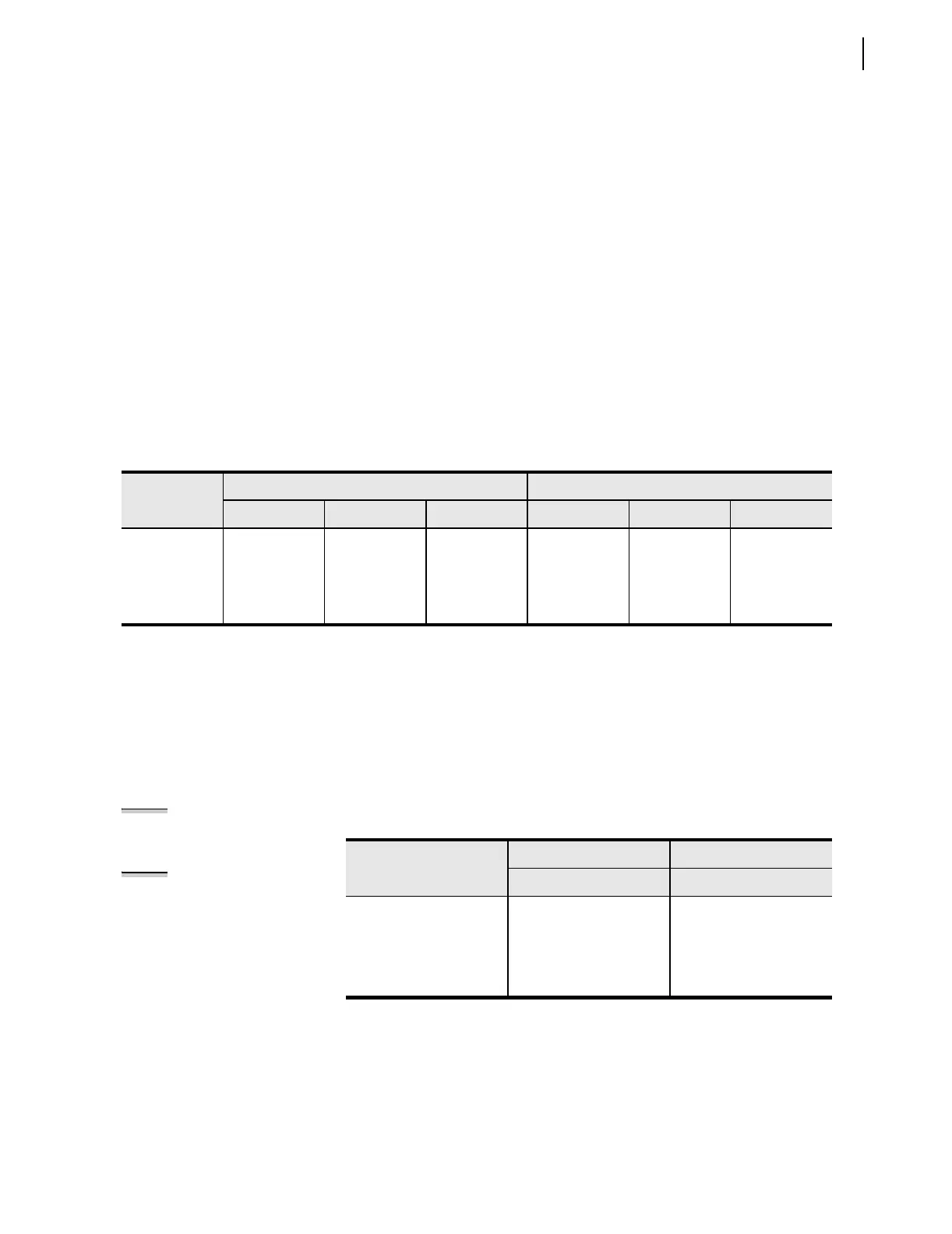
Table 2.9 Jumper Positions for Breaker OPEN/CLOSE Indication
Option (ac/dc)
BREAKER OPEN LED
a
a
The front-panel label for these Breaker Status LEDs may differ from the factory default names if user-configurable labels are used. See
User-Configurable Label Option for the Front Panel on page 2.9.
BREAKER CLOSED LED
a
JMP4 JMP1 JMP2 JMP6 JMP5 JMP3
24 V Installed Installed Installed Installed Installed Installed
48 V Not Installed Installed Installed Not Installed Installed Installed
110/125 V Not Installed Not Installed Installed Not Installed Not Installed Installed
220/250 V Not Installed Not Installed Not Installed Not Installed Not Installed Not Installed
Table 2.10 Jumper Positions for Arc Suppression
Option
{TRIP} pushbutton {CLOSE} pushbutton
JMP8 JMP7
Arc Suppression Enabled
(Factory Default)
dc operation only
Installed Installed
Arc Suppression Disabled
ac operation
Not Installed Not Installed
NOTE: With arc suppression
enabled, the corresponding output
polarity marks must be followed
when wiring the control.
NOTE: Arc suppression should be
disabled when activating high
impedance (> 100 kΩ) loads.

 Loading...


