2.41
Date Code 20080103 Instruction Manual SEL-351S Relay
Installation
Circuit Board Connections
Step 12. When finished, slide the drawout assembly into the relay
chassis.
Step 13. Reconnect the cables removed in Step 5, Step 8, and Step 9, and
replace the relay front-panel cover.
Step 14. Replace any cables previously connected to serial ports.
Step 15. Replace any rear-panel connectors removed in Step 6.
Step 16. Reenergize the relay. (On plug-in connector versions, replace
the power connector at rear-panel terminals Z25 and Z26.)
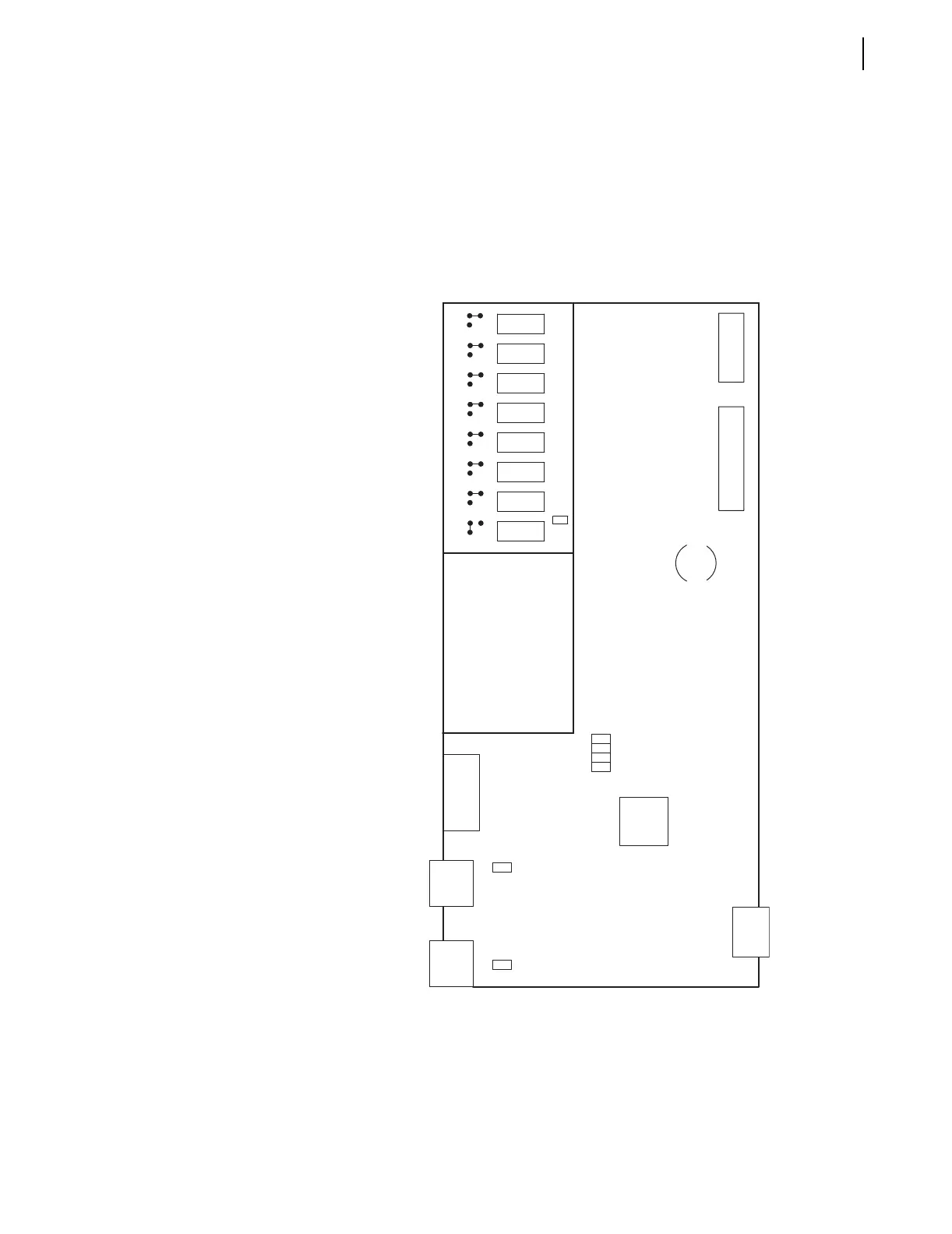
Figure 2.32 Jumper, Connector, and Major Component Locations on the
SEL-351S Main Board
C
μ
Optoisolated Inputs
J1
A
U46
Serial
Port F
(EIA-232)
Serial
Port 3
(EIA-232)
Serial
Port 2
(EIA-232)
Serial
Port 1
(EIA-485)
J7
Analog
Connector
Clock
Battery
B1
J8/J9
J10
Power-I/O
Connector
B
C
D
JMP1
JMP23
JMP21 JMP22 JMP25 JMP26 JMP27 JMP29
Output Contacts
JMP6
OUT101
ALARM
OUT107
OUT106
OUT105
OUT104
OUT103
OUT102
JMP2
JMP2JMP2
B
A
B
A
B
A
B
A
B
A
B
A
B
A
B
A



 To Next Page