2.38
SEL-351S Relay Instruction Manual Date Code 20080103
Installation
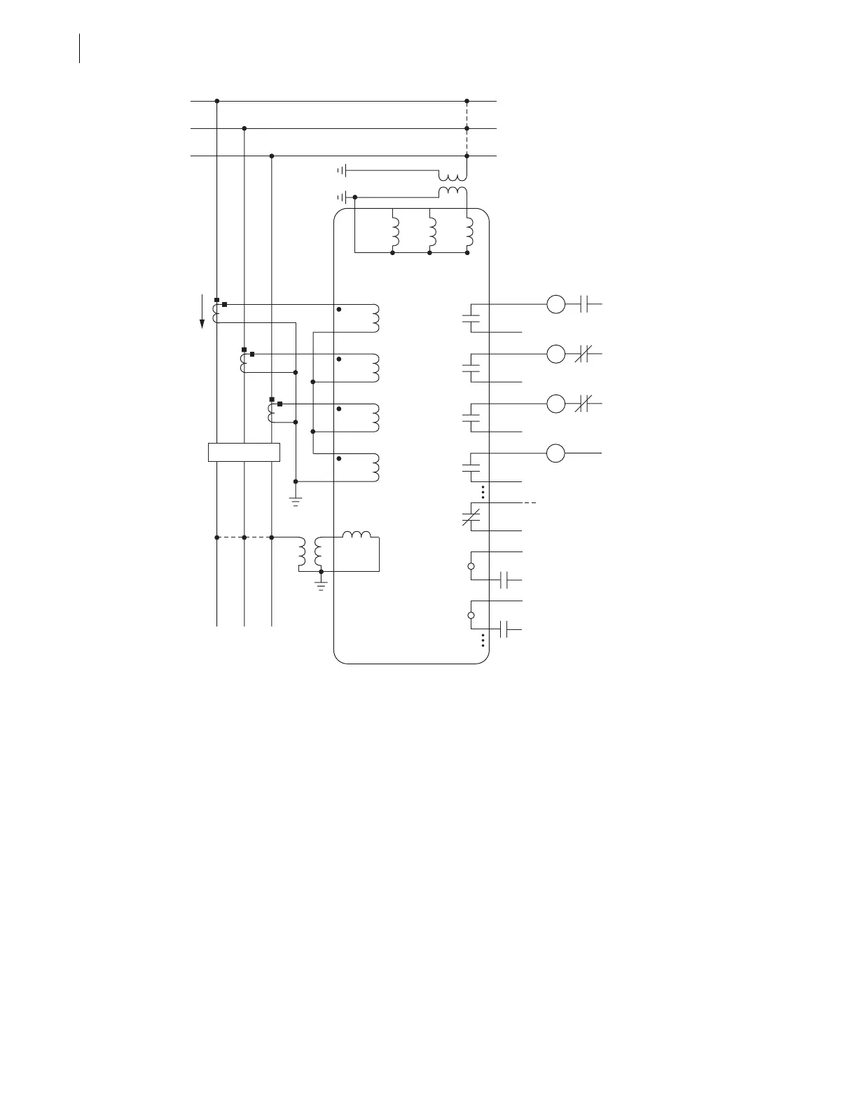
SEL-351S AC/DC Connection Diagrams for Various Applications
Voltage must be applied between relay terminals VA and N (Z09 and Z12, respectively) in order for the underfrequency
elements to operate. Make group setting VNOM = OFF to allow the undervoltage block for the frequency elements to
operate off one phase only (if only connecting one phase voltage to the relay).
The phase of the single-phase voltage connected to VA-N does not matter. For example, it could come from VB, VCA, or
from a station service transformer (suitably fused). It should come from the same bus section that the associated
breaker is connected, preferably from the “normally hot” side.
In the configuration shown, only non-directional overcurrent protection is possible. The fault locator logic and the load
encroachment element are also disabled.
Voltage Channel VS does not need to be connected. Here, it is shown connected for use in voltage and synchronism check
elements and voltage metering. See Synchronism Check VS Connection (Global Setting VSCONN = VS) and Broken-Delta
VS Connection (Global Setting VSCONN = 3V0) on page 2.20.
Current Channel IN does not need to be connected. Channel IN provides current I
N
for the neutral ground overcurrent
elements. Separate from Channel IN, the residual ground overcurrent elements operate from the internally derived
residual current I
G
(I
G
= 3I
0
= I
A
+ I
B
+ I
C
). But, in this residual connection example, the neutral ground and residual
ground overcurrent elements operate the same because I
N
= I
G
.
Figure 2.30 SEL-351S Provides Underfrequency Load Shedding, Overcurrent Protection, and Reclosing for a
Utility Distribution Feeder (Single Voltage Connection)
TC
Trip
Coil
52A
(+)
(—)
Trip
Circuit
IA
C
B
A
NVCVB
SEL-351 RELAY
VA
OUT101
Forward Tripping Direction
CC
Close
Coil
52B
(+)
(—)
Close
Circuit
IB
OUT102
86
Lock
Out
86B
(+)
(—)
Breaker
Failure
Trip
Circuit
TX
(—)
Comm.-
Assisted
Trip
Scheme
IC
OUT103
IN
VS
NS
LINE
52
(+)
OUT104
(+)
52A
to Annunciator, RTU,
or SEL-2032/2030/2020
ALARM
(+)
(—)
Breaker Status
IN101
RX
(+)
(—)
Comm.-Assisted
Trip Scheme
IN102



 To Next Page