EasyManua.ls Logo

Selco NEOMIG 2000 - User Manual

Default Icon
165 pages
Go to English
Print Icon
To Next Page IconTo Next Page
Loading...
Neomig
1600-2000-2200-2400
2000-2400 XP
ISTRUZIONI PER L’USO
INSTRUCTION MANUAL
BETRIEBSANWEISUNG
MANUEL D’INSTRUCTIONS
INSTRUCCIONES DE USO
MANUAL DE INSTRUÇÕES
GEBRUIKSAANWIJZING
BRUKSANVISNING
BRUGERVEJLEDNING
BRUKSANVISNING
KÄYTTÖOHJEET

Table of Contents

Question and Answer IconNeed help?

Do you have a question about the Selco NEOMIG 2000 and is the answer not in the manual?

Summary

Safety Symbols

1 WARNING

Operator and Bystander Protection

Safety measures for operators and bystanders from welding hazards like arc rays and noise.

Fumes, Gases, Fire, and Explosion Prevention

Guidelines for ventilation, protection, and preventing fires/explosions from welding.

2 INSTALLATION

Power Supply Connection and Voltage Selection

Instructions for connecting the power supply and selecting the correct mains voltage.

Earthing Requirements

Crucial safety information regarding the proper earthing of the system and its components.

Commissioning and Start-up Procedures

Step-by-step guide for initial setup and starting the welding machine.

3 MACHINE DESCRIPTION

STANDARD Front Control Panel

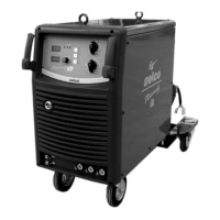
Description and function of the controls and indicators on the STANDARD model's front panel.

XP Front Control Panel and SYNERGY Mode

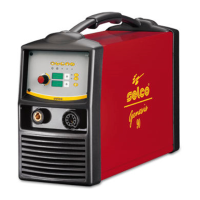
Details of the controls and indicators on the XP model's front panel, including SYNERGY mode.

4 MAINTENANCE

Routine Maintenance Procedures

Guidelines for periodic checks and cleaning of the welding equipment.

5 POSSIBLE ELECTRICAL FAILURES

Troubleshooting Power and Command Issues

Resolving issues with machine power, commands, and arc striking.

6 POSSIBLE FAULTS IN THE MIG WELDING

7 CONTINUOUS WIRE WELDING THEORY

Understanding Welding Parameters

Relationship between voltage, wire feed speed, and current for optimal welding results.

GUIDE TABLE FOR WELDING PARAMETERS

Parameter Selection by Wire Diameter and Application

Table guiding the choice of welding voltage, current, and process based on wire size.

8 TECHNICAL SPECIFICATIONS

Electrical Schematic Diagrams

NEOMIG 1600 Schematic Diagram

Electrical schematic diagram for the NEOMIG 1600 model.

Wire Feed Unit Components

Symbol Key

Selco NEOMIG 2000 Specifications

General IconGeneral
BrandSelco
ModelNEOMIG 2000
CategoryWelding System
LanguageEnglish

Related product manuals