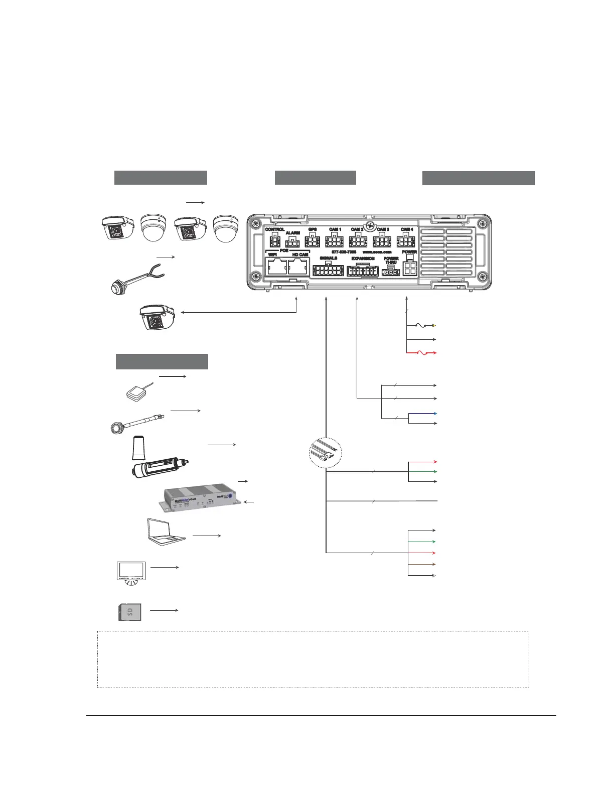
1.3. Installation Diagram
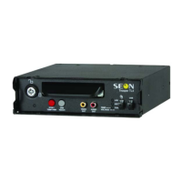
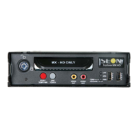
Trooper® TL-HD
Typical System Setup
Vehicle Electrical Interface
Peripherals
Seon System
Supports Four
Analog Cameras
GPS Receiver
*1
Adapter
Harness
*2
Red - Not used
Green - Vehicle + 12V *6
Black - Battery Negative
3 wires
WAKE (Optional)
Alarm Switch
*1 For speed tracking, use a GPS receiver.
*2 The Diagnostic Button and alarm input harness are optional and require the adapter harness.
*3 An optional Smart-Reach Cellular, Laptop can be used from the Ethernet outputs located on the front panel.
*4 An optional Video Monitor can be used from the video outputs located on the front or back panel.
*5 12V 150mA source or 0V 350mA sink
*6 Wake up input, active high (5 - 32V edge triggered)
Use Seon approved cards only
Portable Video Monitor *
4
Diagnostic Button*
2
Optional Accessories
To DVR GPS Input
To DVR
ALARM
Input
To DVR
Camera
Inputs
To DVR
SIGNALS
Input
Laptop *
3
To DVR VIDEO OUT
TL-HD DVR Rear Panel
To Adapter
Harness
DIAGNOSTIC
Input
To DVR LAN
Input
Smart-Reach Lite
(Wi-Fi) *
3
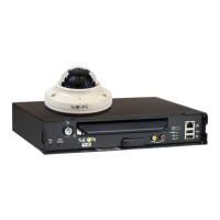
CHW HD
Camera
To DVR
HD CAM
Input
To DVR
POWER
Input
1x5 Microfit
DIAGNOSTIC/RGY (Optional)
Black - Left Turn
Green - Stop
Red - Brake Signal
Brown - Warning
White - Right Turn
5 wires
SIGNALS
Red - Vehicle + 12V
10A
3 wires
Yellow - Vehicle Switched + 12V
Black - Battery Negative
POWER
1A
Smart-Reach
Cellular Modem *
1
To DVR WIFI
Input
To DVR LAN
Input
To DVR
EXPANSION
Input
2x3 Microfit
Rear Vision System (Optional)
1x4 Microfit
Student Track (Optional)
Blue - Vehicle + 12V (Optional) *5
Black - Battery Negative (Optional)
2 wires
From DVR
Power Thru output
SD Card *
7
To DVR SD CARD Input (DVR Front)
*7