10
Service
Line connection energy supply
Operating Instructions – MOVIPRO
®
PHC11A-..M1-..2A-A1/..
93
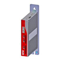
Replacing the unit
Proceed as follows to replace the unit:
1. Disconnect the unit and remove it from the system.
2. Loosen the connection of the ID module and remove it from the X4401.
3. Plug the ID module into connection X4401 of a new unit and tighten the screw.
4. Install the new unit in the system and connect it.
5. Switch on the new unit.
For detailed information, refer to the "Parameterizable Plant Software MOVIVISION
®
Version 2.0 – MOVIPRO
®
(Software Interface)" manual.
10.1.3 Display
The status display indicates the status of the unit. It is operated by the processor unit.
Refer to the software documentation for detailed information on possible error mes-
sages.
10.1.4 Fault information of the frequency inverter
WARNING
Risk of automatic restart of the drive after fault elimination or after a reset.
Fatal or severe injuries and damage to property.
• Disconnect the unit from the supply system before rectifying a fault if automatic
restart of the driven machine after fault elimination is not permitted for safety rea-
sons.
• After a reset, make sure that the drive can start up automatically depending on
the setting.
For information on the functionality of inverters and possible errors, refer to the
"MOVIDRIVE® MDX60B/61B" system manual.
20278543/EN – 09/2014

 Loading...


