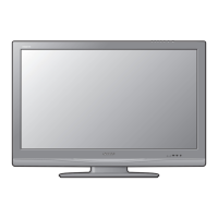
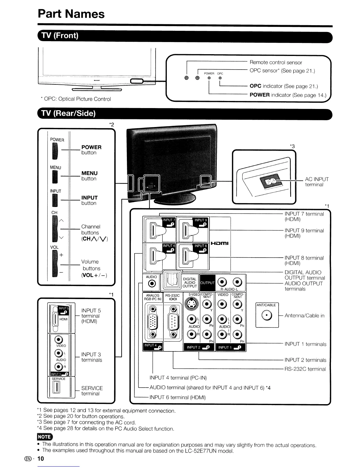
Part Names
TV (Front)
C!)
Q)
I 1 OPC indicator
(See
page 21.)
------
POWER indicator
(See
page 14.)
~
• OPC: Optical Picture Control
'1---------
Remote control sensor
'I
-------
OPC sensor*
(See
page 21.)
POWER
ope
e _
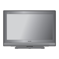
TV (Rear/Side)
*2
*1
*3
ANT/CABLE
o
"-
Antenna/Cable
in
~T~
~T~
AUDIO
PB
AUDIO
PB
~~~ ~~~
PA PA
>...------
INPUT 1 terminals
I----\--------INPUT
9 terminal
(HDMI)
L-
INPUT 2 terminals
L-
RS-232C terminal
INPUT 4 terminal (PC-IN)
AUDIO terminal (shared for INPUT 4 and INPUT
6)
*4
INPUT 6 terminal
(HDMI)
r==....1::::::::::::::::::;::::::::::::::::::::::::::::::::::===:::::--------
INPUT 7 terminal
(HDMI)
I---+---------INPUT
8 terminal
(HDMI)
=====t==:::::::;------
DIGITAL AUDIO
~
OUTPUT terminal
~ ~
11------
AUDIO OUTPUT
!--
__
~;rF===='T=~~~~~:§R~.A~UD~IO§:-~L
~
terminals
VIDEO
c~~~.p-
~~
y
*1
SERVICE
terminal
INPUT 3
terminals
INPUT 5
terminal
(HDMI)
Volume
--:+--
buttons
(VOL+/-)
PIOWE---i7R
11_
POWER
button
MENU
I
MENU
-+;--
button
"
"-
e
VIDEO
~~
"-
AUDIO
e~
3
SERVICE
m
"-
INPUT
I
INPUT
-+;--
button
CH
1
AV-----'-'-------
----;-;-
Channel
buttons
(CH/VV)
VOL
I:
II
*1
See pages
12
and 13 for external equipment connection.
*2
See page 20 for button operations.
*3
See page 7 for connecting the AC cord.
*4
See page 28 for details on the PC Audio Select function.
ImD
• The illustrations
in
this operation manual are for explanation purposes and may vary slightly from the actual operations.
• The examples used throughout this manual are based on the LC-52E77UN model.
(®-
10