(3) Developing Bias Adjustment
1 Set the measuring range of the digital multimeter to 300 Vdc or
more.
2 Apply the probes to the developing bias output check pin (CP-B)
and the chassis(GND) of the high voltage unit.
3 Perform Simulation 8-1. (The developing bias voltage is output
for 30 seconds.
4 Adjust VR301 for developing bias control so that the output
voltage is –300±10V.
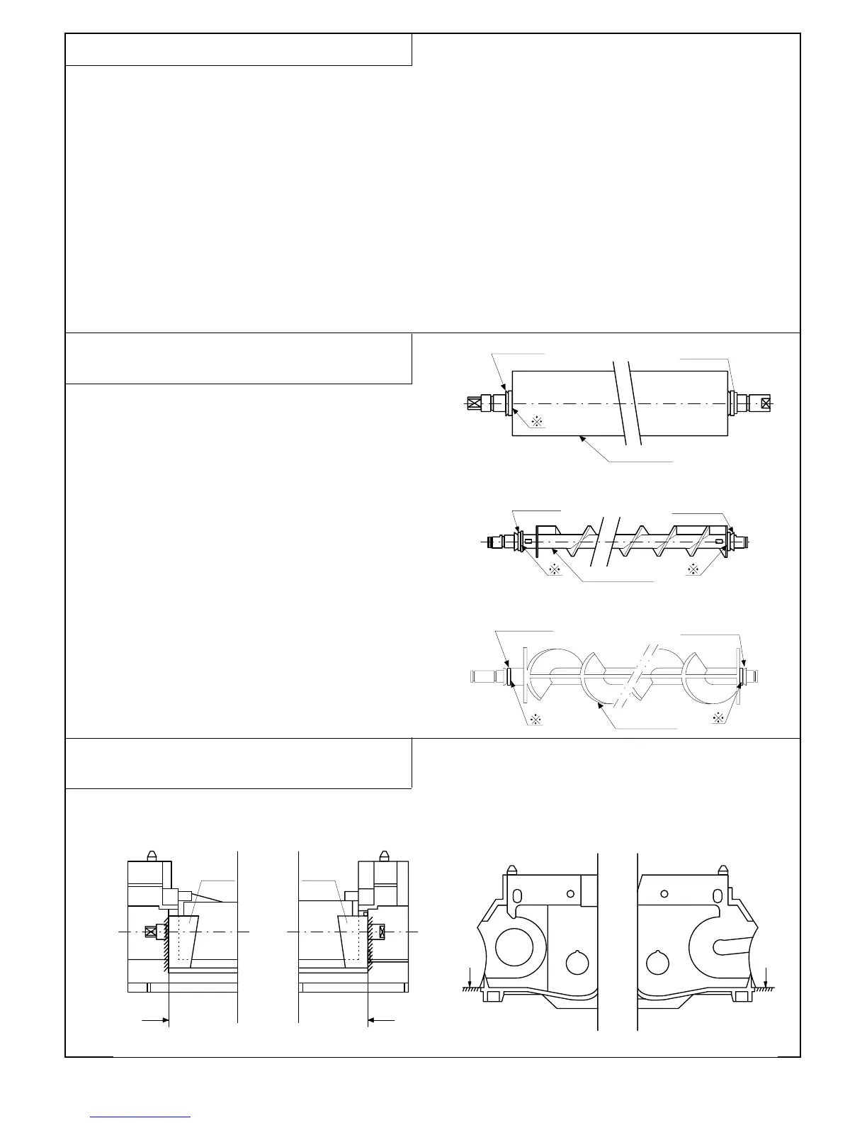
(4) Notes on installing various rollers of the
developing unit
(1) V-rings must be attached in the correct direction.
(2) No gap must exist at ❈ between the V-ring and the roller.
(3) When attaching φ8-ring PRNGP0013FCZZ, φ8-ring
PRNGP0022FCZZ and φ6-ring PRNGP0015FCZZ to the
developing magnet roller,
1) the direction of the V-ring must be as shown in the upper
figure.
2) no gap must exist at ❈ between the V-ring and the roller.
(5) Notes on applying the developing side seals
(front and rear)
(1) The side seal must be applied on a surface which is free of oil,
grease and foreign matter.
(2) The side seal must be securely attached to prevent it from
coming off.
V-ring Φ8
V-ring
Φ
6
V-ring
Φ
8
Rear
Front
Magnet roller
V-ring
Φ
6
Rear Front
Roller S (X2)
V-ring
Φ
6
V-ring
Φ
6
Rear
Front
Roller MX
D B
C A
Rear Front
Front
Rear
7 – 2