Chapter 1 Principles, Description, and Functions of the IRAffinity-1
1-10
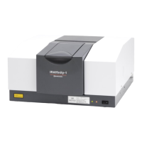
IRAffinity-1
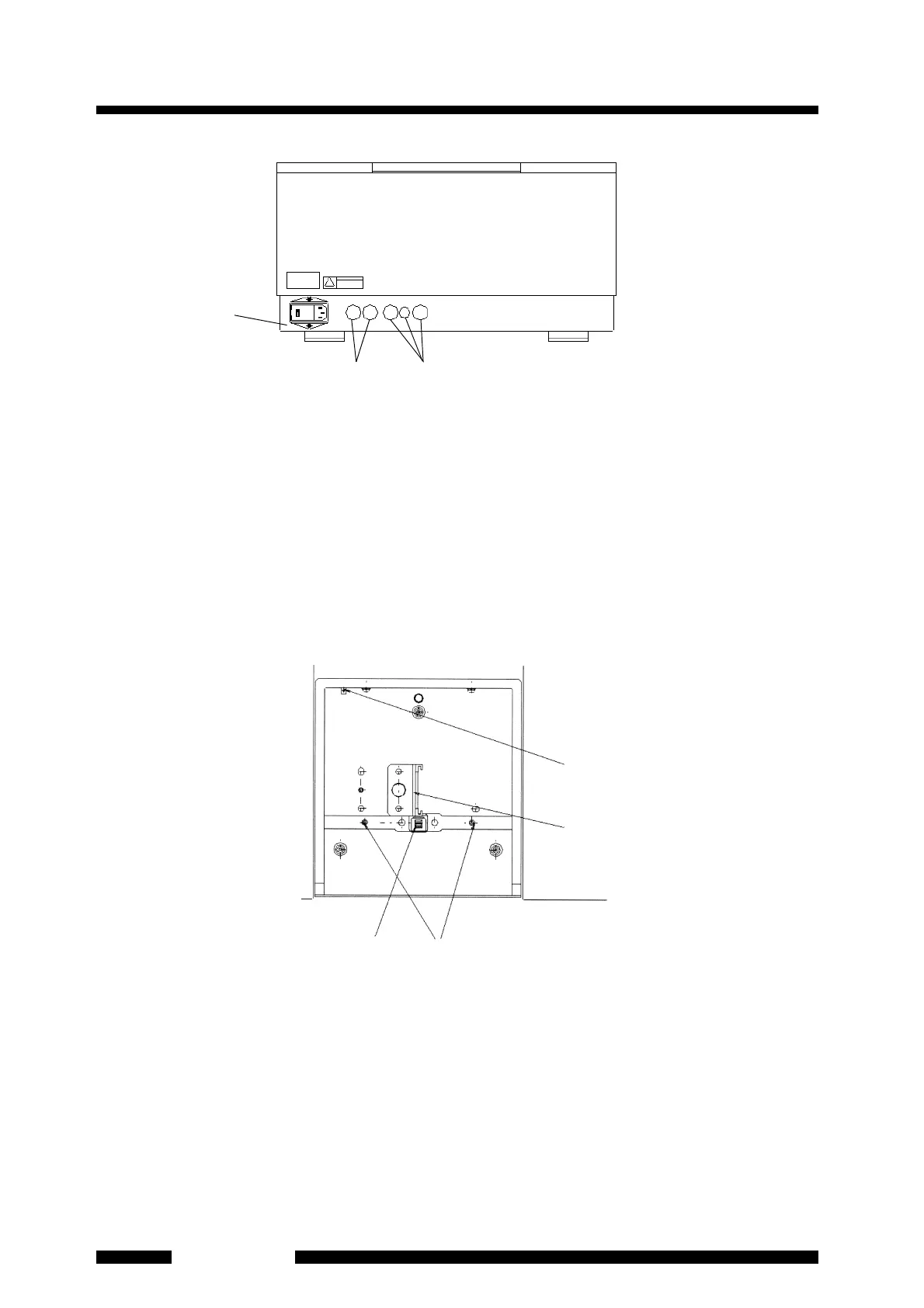
Fig. 1.6 Appearance of Interferometer (Rear View)
(1) AC inlet (with fuse holder) : Connect the power cable here. Two fuses are accommodated
here.
(2) Optional connector mounting holes : Connect the connector here to use an optional MCT
detector such as infrared microscope. Caps are attached here. Do not remove them unless
using options.
(3) Purge tube inlets : Insert tubes here and connect the tubes to the piping inside the
interferometer to purge the interferometer or the sample compartment with dry air, etc.
1.5.2 Inside of Sample Compartment
Fig. 1.7 Inside View of Sample Compartment
(1) Cassette : When using a liquid cell or 5 cm gas cell slide it into the groove here from the top.
When using a KBr tablet, insert it into the cassette hole from the right side. Remove the M5
mounting screws to remove the cassette. When using a 10 cm gas cell, install the cassette to
the mounting holes on the left side of the usual installation position. When there are plays
between a cassette and your accessory, the reproducibility is improved by mounting the
accessory on the backward or forward of the casette. An optional cassette (206-17384)
improves reproducibility more.
(3)
(1)
(2)
(2)(3)
(4)
(1)