Chapter 5 Operating Instructions
C4000 Micro/Basic/Basic Plus/Eco
30 © SICK AG • Industrial Safety Systems • Germany • All rights reserved 8009423/YT79/2016-03-14
Subject to change without notice
Electrical installation
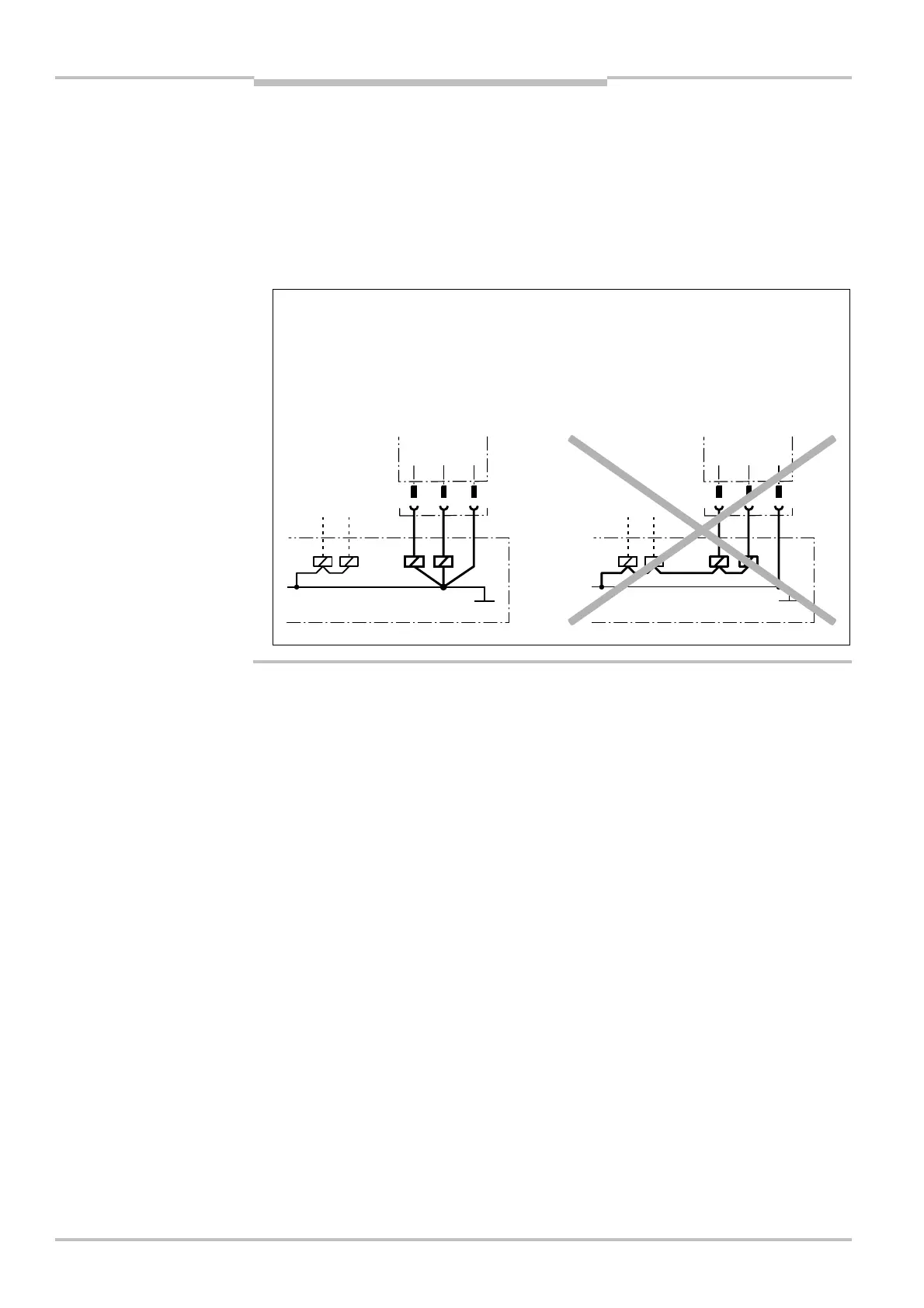
Prevent the formation of a potential difference between the load and the protective
device!
⋅ If you connect loads that are not reverse-polarity protected to the OSSDs or the safety
outputs, you must connect the 0 V connections of these loads and those of the corres-
ponding protective device individually and directly to the same 0 V terminal strip. This is
the only way to ensure that, in the event of a defect, there can be no potential diffe-
rence between the 0 V connections of the loads and those of the corresponding protec-
tive device.
• The two outputs are protected against short-circuits to 24 V DC and 0 V. When the light
path is clear, the signal level on the outputs is HIGH DC (at potential), when the light
beams are interrupted or there is a device fault the outputs are LOW DC.
• The safety light curtain C4000 meets the interference suppression requirements (EMC)
for industrial use (interference suppression class A). When used in residential areas it
can cause interference.
• To ensure full electromagnetic compatibility (EMC), functional earthing (FE) must be
connected.
• The external voltage supply of the device must be capable of buffering brief mains vol-
tage failures of 20 ms as specified in EN 60 204-1. Suitable power supplies are availa-
ble as accessories from SICK (SICK Power Supply 50 W (Part number 7028789)/SICK
Power Supply 95 W (Part number 7028790)).
Notes
Safety output 1
OSSD2
Safety output 2
Safety output 1
OSSD2
Safety output 2