Chapter 3 Operating Instructions
C4000 Micro/Basic/Basic Plus/Eco
18 © SICK AG • Industrial Safety Systems • Germany • All rights reserved 8009423/YT79/2016-03-14
Subject to change without notice
Product description
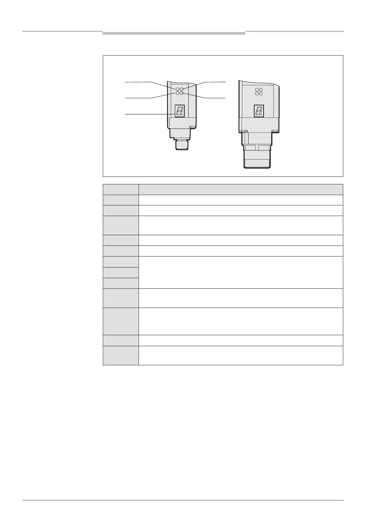
3.5.2 Status indicators of the receiver
Display Meaning
O Orange Cleaning or realignment required
Ö Yellow Reset required
O Red
System providing signals for shutting down the machine
(switching output off)
O Green System enabled (switching output on)
δ System error. The device is defective. Replace the receiver.
/
0
1
Poor alignment to sender.
Please refer to chapter 6.2 “Aligning sender and receiver” on page 37.
∩
Approx. 1 s. Device waits for start-up configuration (Only after switching on.
See section 7.4 “Start-up configuration” on page 40).
γ
Approx. 0.5 s. Only for systems with a resolution of 14 mm and a scanning
range of 1–5 m: Operation with large protective field width (only after
switching on)
τ Non-coded operation (only after switching on)
Other
displays
All other displays are error messages. Please refer to chapter “Fault
diagnosis” on page 43.
the receiver
the receiver
display