Chapter 5 Operating Instructions
C4000 Micro/Basic/Basic Plus/Eco
32 © SICK AG • Industrial Safety Systems • Germany • All rights reserved 8009423/YT79/2016-03-14
Subject to change without notice
Electrical installation
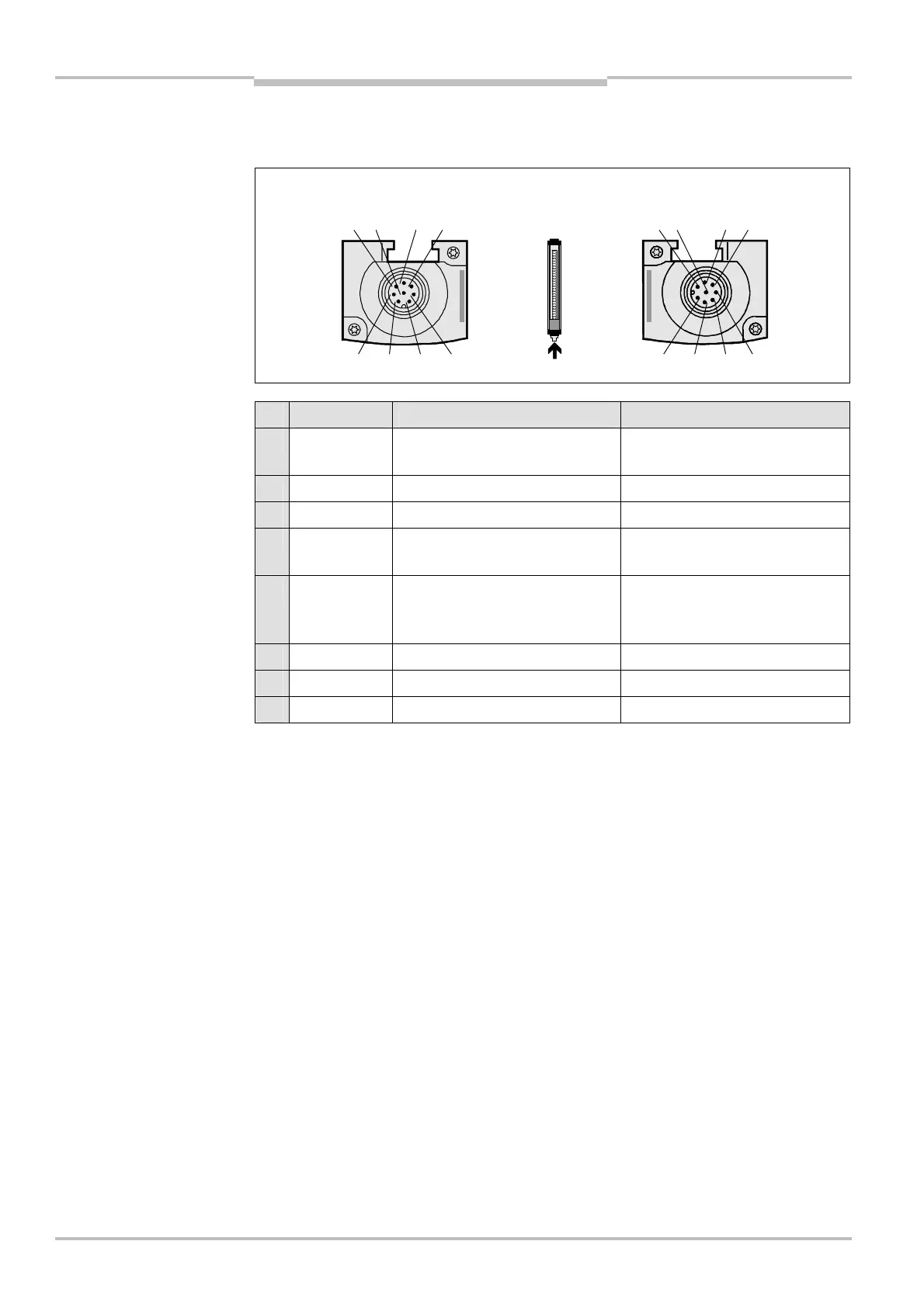
5.3 System connection C4000 Micro/Basic Plus
(M12 × 7 + FE)
Pin Wire colour s Sender r Receiver
1 White Reserved
Reset/restart or start-up
configuration 2
2 Brown 24 V DC input (voltage supply) 24 V DC input (voltage supply)
3 Green Reserved Start-up configuration 1
1)
4 Yellow Reserved
External device monitoring
(EDM)
1)
5 Grey
Test input:
0 V: External test active
24 V: External test inactive
OSSD1 (switching output 1)
6 Pink Reserved OSSD2 (switching output 2)
7 Blue 0 V DC (voltage supply) 0 V DC (voltage supply)
FE Screen Functional earthing Functional earthing
1)
Pins 3 and 4 of the receiver connection are jumped internally.
system connection
C4000 Micro/Basic Plus
(M12
×
7 + FE)
system connection
C4000 Micro/Basic Plus
(M12
×
7 + FE)