Operating Instructions Chapter 6
C4000 Micro/Basic/Basic Plus/Eco
8009423/YT79/2016-03-14 © SICK AG • Industrial Safety Systems • Germany • All rights reserved 37
Subject to change without notice
Commissioning
6 Commissioning
Commissioning requires a thorough check by qualified safety personnel!
Before you operate a system protected by the safety light curtain C4000 for the first time,
make sure that the system is first checked and approved by qualified safety personnel.
Please read the notes in chapter “On safety” on page 8.
6.1 Display sequence during start-up
After the system is activated, sender and receiver go through a power-up cycle.
The 7-segment display indicates the device status during the power-up cycle.
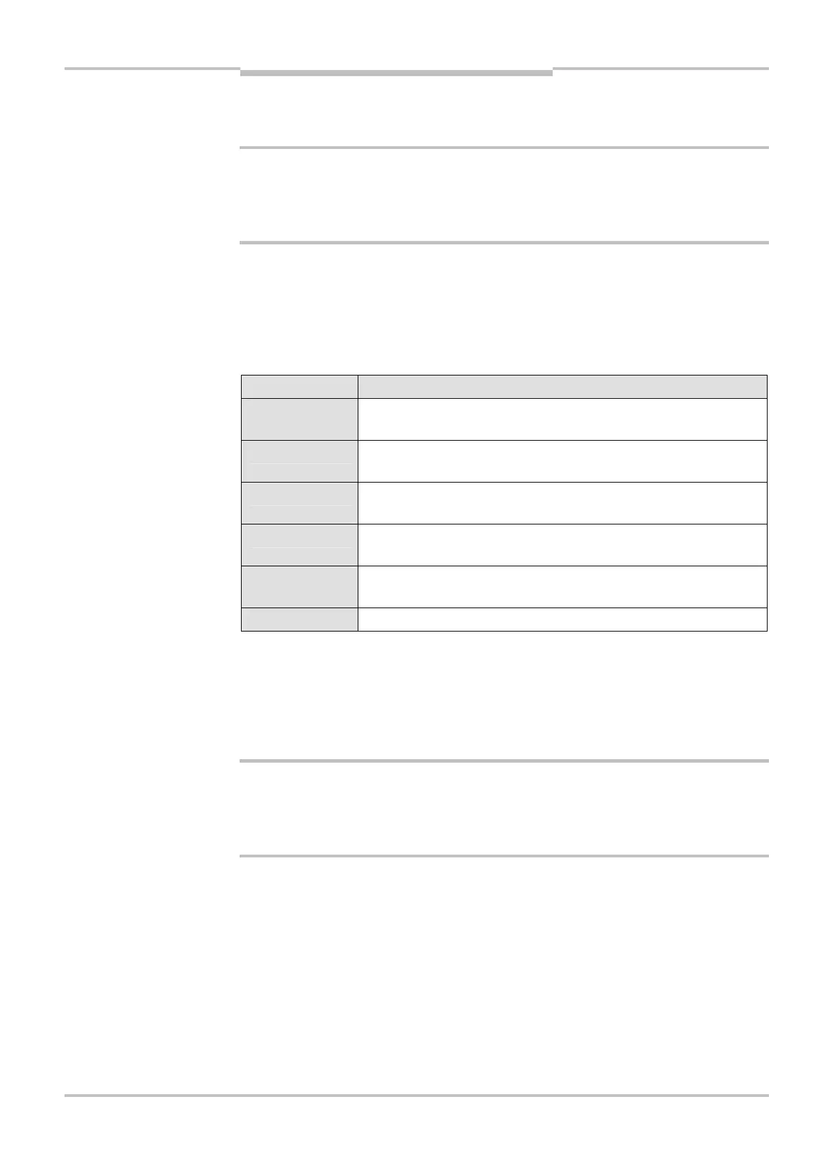
The display values have the following meaning:
Display Meaning
, , , ,
, , ,
Testing the 7-segment display. All segments are activated
sequentially.
γ
Approx. 0.5 s. Only for systems with a resolution of 14 mm and a
scanning range of 1–5 m: Operation with large protective field width
τ
Approx. 0.5 s. Uncoded operation. This display is due to reasons of
compatibility to other C4000 systems.
∩
Approx. 1 s. Device waits for start-up configuration (see section 7.4
“Start-up configuration” on page 40).
/, 0 or 1
Receivers only: Receiver-sender alignment incorrect (see “Aligning
sender and receiver” below).
Other display Device error. See “Fault diagnosis” on page 43.
6.2 Aligning sender and receiver
After the light curtain has been mounted and connected, the sender and receiver must be
aligned precisely in relation to each other.
How to align sender and receiver in relation to each other:
Secure the plant/system. No dangerous movement possible!
Make sure that the dangerous state of the machine is (and remains) switched off! During
the alignment process, the outputs of the safety light curtain are not allowed to have any
effect on the machine.
⋅ Loosen the clamping bolts which hold the light curtain in place.
⋅ Switch on the power supply to the light curtain.
⋅ Watch the alignment information on the 7-segment display of the receiver (see Tab. 13).
Correct the alignment of the sender and receiver, until the 7-segment display goes off.
⋅ Using the clamping bolts, fix the light curtain in place.
⋅ Switch the power supply off and then back on again and check via the 7-segment
display whether the alignment is correct after tightening the clamping bolts (Tab. 13).
a
WARNING
during the power-up cycle
a
WARNING