The device basically detects the codes on any side on an object (single side reading).
The objects can be at rest or moved in a conveyor system.
By combining several devices via CAN, multiple sides of an object can be recorded in
one passage (multi-side reading).
To capture the codes, the device generates a scan line (line scanner).
In the raster scanner version, the device generates eight scan lines. The lines are offset
parallel to each other.
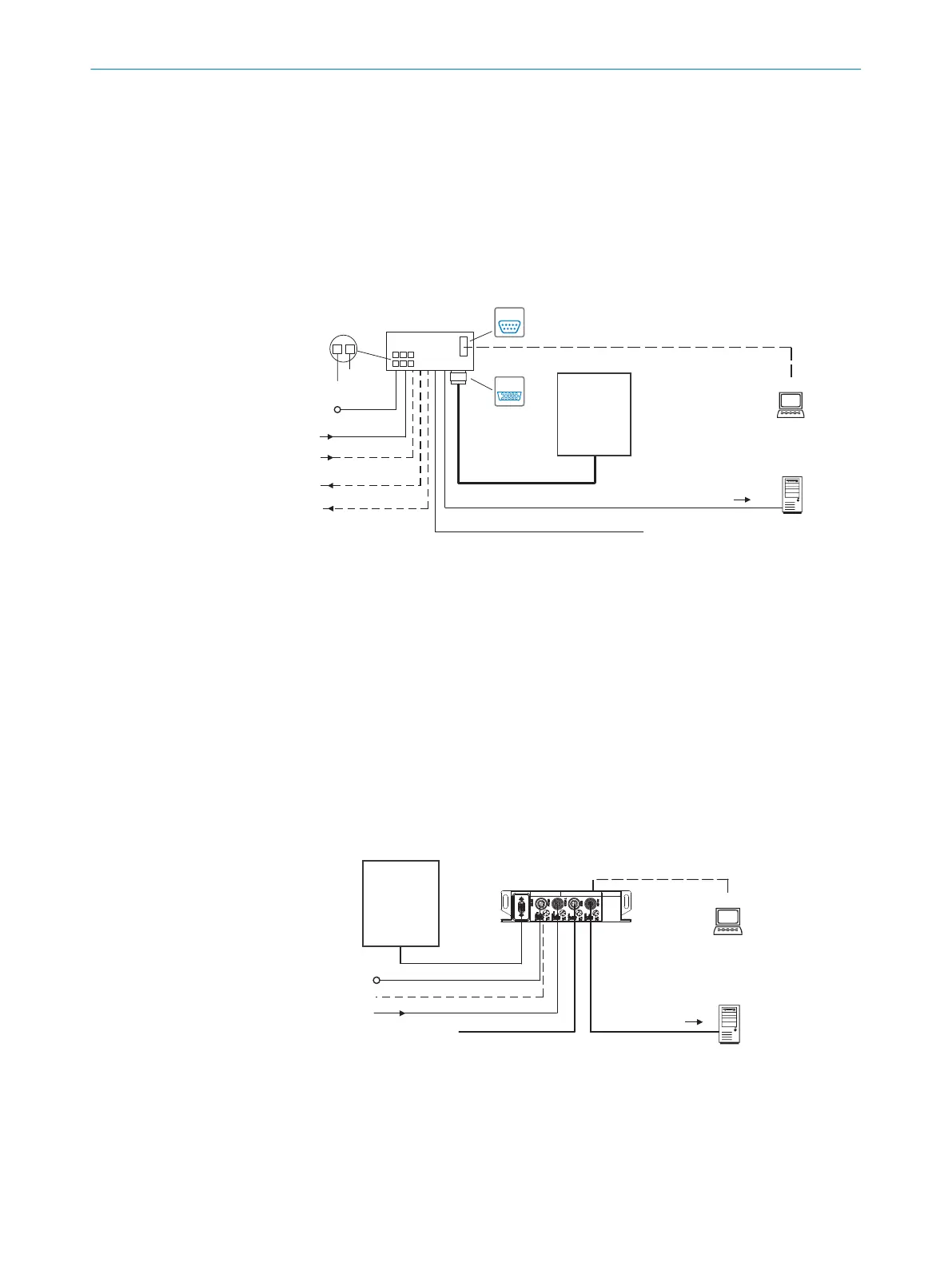
Block diagrams
Input 2 ß
Input 1 à
Output 1 9
Output 2 8
Connection module 1
SerialSerial
Configuration
Diagnostics 3
SOPAS ETSOPAS ET
SerialSerial
...
...
1
2
V
S
GND
HOST
Further data
processing 4
Serial RS-232” (AUX 1)
V
S
á
“Serial RS-232” (Host)
Reading result 6
“CAN” (CLV61x CAN only) 7
CAN Sensor Network 5
Device 2
“Power/RS-232/I/O”
(AUX, Host)
Computer
Figure 6: Facilities for connecting for CLV61x (CAN)
1
Connection module (optional)
2
Device (CLV61x CAN)
3
Configuration or diagnostics
4
Further data processing
5
CAN sensor network
6
Read result
7
CLV61x CAN only
8
Digital output 2, e.g. for connecting an LED
9
Digital output 1, e.g. for connecting an LED
ß
Digital input 2, e.g. for connecting an incremental encoder
à
Digital input 1, e.g. for connecting a read cycle sensor
á
Supply voltage V
S
Configuration
Diagnosis 3
SOPAS ETSOPAS ET
“RS-232/CAN/Power”
PLC
Further data
processing 4
V
S
9
“AUX” (USB)
Reading result 5
CAN Sensor Network 8
Fieldbus
Fieldbus 6
Fieldbus module 2
Input 1 7
Device 1
Computer
Figure 7: Facilities for connecting for CLV61x, FIELDBUS variants
1
Device (CLV61x FIELDBUS)
2
Fieldbus module (CDF600-22xx PROFINET or CDF600-21xx PROFIBUS)
3
Configuration or diagnostics
4
Further data processing
PRODUCT DESCRIPTION 3
8017840/19OF/2021-10-28 | SICK O P E R A T I N G I N S T R U C T I O N S | CLV61x
21
Subject to change without notice

 Loading...


