5
Read result
6
Fieldbus
7
Digital input 1, e.g. for connecting a read cycle sensor
8
CAN sensor network
9
Supply voltage V
S
3.2.4.1 Object trigger control
To start an object-related read operation, the device requires a suitable signal (trigger
source) for reporting an object in the reading field. The start signal is provided by an
external read cycle sensor (e.g. photoelectric sensor) as standard. As soon as an object
has passed the read cycle sensor, the device opens a time window (“reading interval")
for the reading process.
Alternatively, a command via a data interface or the SICK SENSOR network (CAN) starts
the reading process. In Auto pulse mode, the device internally generates the reading
interval itself with an adjustable clock ratio.
The read cycle can be terminated in various ways. In the event of external triggering,
this is carried out via the read cycle source or a command, or internally via a timer or an
evaluation condition that needs to be met.
NOTE
The SOPAS ET configuration software can be used to configure the trigger source.
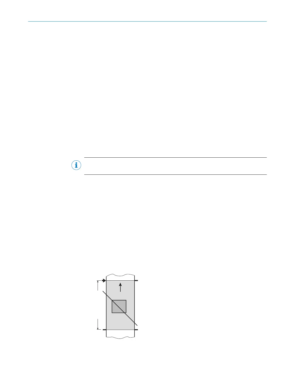
3.2.4.1.1 Reading operation mode
In start/stop mode, there is always only one object in the reading field during the
reading process. This allows all read codes to be uniquely assigned to the object. As
standard, starting and stopping of the reading process are controlled by one or two
read cycle sensors at the start and end of the reading field.
The distance between the read cycle sensors determines the size of the reading field.
The reading process can alternatively be controlled with command strings via the data
interface.
The device outputs the read results at the following time:
•
At the end of the read cycle, the trailing edge of the object has left the end of the
reading field
•
or by fulfilling the Good Read condition during the read cycle
Data
output 5
Trigger 2:
Stop
reading 2
Trigger 1:
Start
reading 3
Reading field 4
Start/Stop operation 1
Figure 8: Start/stop operating mode of the device in stand-alone operation
1
Start/stop operation
2
Trigger 2: Stop reading
3
Trigger 1: Start reading
3 PRODUCT DESCRIPTION
22
O P E R A T I N G I N S T R U C T I O N S | CLV61x 8017840/19OF/2021-10-28 | SICK
Subject to change without notice

 Loading...


