S > 500 mm, therefore:
S = 1,600 mm/s × 0.32 s + 8 × (14 mm – 14 mm) = 512 mm
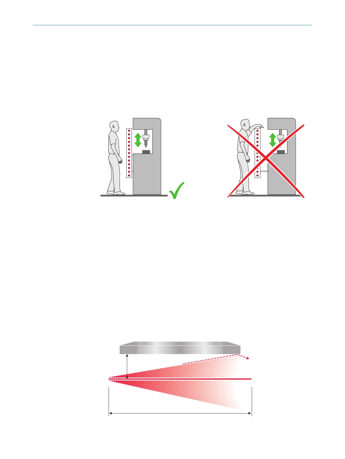
4.3.2.2 Taking reach over into account
In accordance with ISO 13855, it must not be possible to defeat the ESPE. If access to
t
he hazardous area by reaching over a protective field cannot be prevented, the height
of the protective field and minimum distance of the ESPE must be determined. This is
done by comparing the calculated values based on the possible detection of limbs or
body parts with the values resulting from reaching over the protective field. The greater
value resulting from this comparison must be used.
Figure 13: Representation of the accessibility of electro-sensitive protective device by reaching
o
ver. Left: Protective field that cannot be reached over. Right: Protective field that can be reached
over.
4.3.3 Minimum distance from reflective surfaces
Overview
T
he light beams from the sender unit may be deflected by reflective surfaces and dis‐
persive media. This can prevent an object from being detected.
Therefore, all reflective surfaces and objects (e.g. material bins, machine table, etc.)
must maintain a minimum distance (a) from the protective field. This minimum dis‐
tance (a) must be maintained on all sides of the protective field. This applies in horizon‐
tal, vertical and diagonal directions as well as at the end of the safety light curtain. The
same area must be free of dispersive media (e.g., dust, fog, or smoke).
The minimum distance (a) depends on the distance (D) between the twin sticks (protec‐
tive field width).
The weld spark guard can influence the optical properties of the safety light curtain,
meaning that reflective surfaces have to observe a larger minimum distance.
Figure 14: Minimum distance from reflective surfaces
PROJECT PLANNING 4
8012624/10OM/2018-08-09 | SICK O P E R A T I N G I N S T R U C T I O N S | miniTwin4
25
Subject to change without notice