6.2 System connection
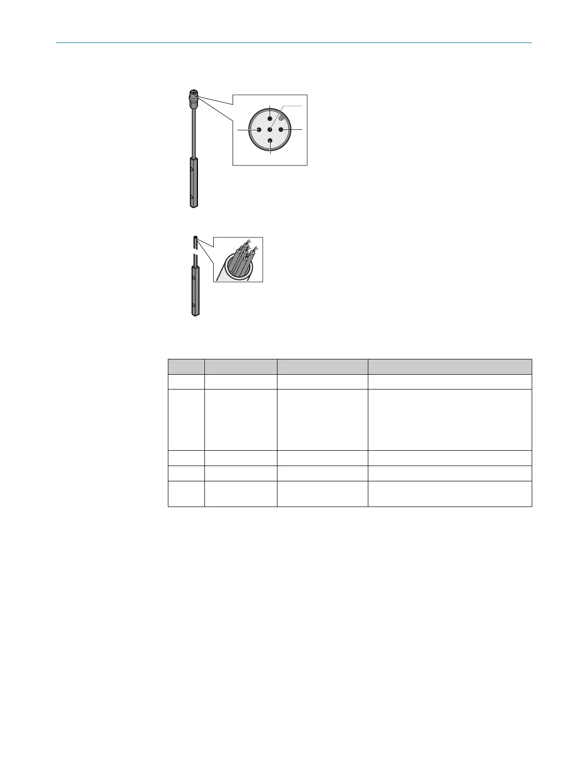
Figure 54: System connection pin assignment
Figure 55: System connection wires
Table 7: System connection pin assignment
Pin Wire color Meaning Comment
1 Brown 24 V DC input Voltage supply of the miniTwin4
2 White Multifunctional con‐
nec
tion
•
C
onnection of the reset button
Or:
•
EDM connection
Or:
•
0 V DC (no function active)
3 Blue 0 V DC Voltage supply of the miniTwin4
4 Black OSSD Switching output
FE Gray Functional earth To fulfill the EMC requirements, the func‐
t
ional earth (FE) must be connected.
Pre-assembled cables with open ends are available for connecting applications.
Further topics
•
"R
estart interlock", page 14
•
"External device monitoring (EDM)", page 14
•
"Cascading", page 15
•
"Connectivity", page 102
•
"Test rod check", page 41
6 ELE
CTRICAL INSTALLATION
62
O P E R A T I N G I N S T R U C T I O N S | miniTwin4 8012624/10OM/2018-08-09 | SICK
Subject to change without notice