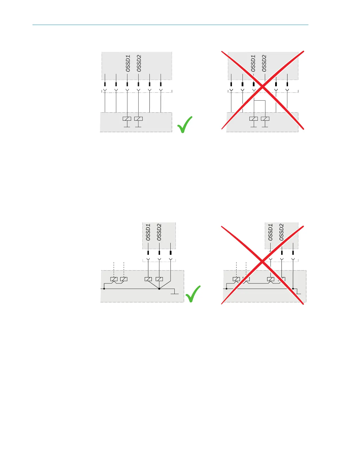
Example: Isolated connection of OSSD1 and OSSD2
Figure 52: Dual-channel and isolated connection of OSSD1 and OSSD2
Avoiding any potential difference between load and protective device
•
If t
he loads are connected to the OSSDs (switching outputs) that then also switch if
controlled with negative voltage (e.g., electro-mechanical contactor without reverse
polarity protection diode), the 0 V connections of these loads and those of the cor‐
responding protective device must be connected separately and also directly to
the same 0 V terminal strip. In the event of a fault, this is the only way to ensure
that there can be no potential difference between the 0 V connections of the loads
and those of the corresponding protective device.
Figure 53: No potential difference between load and protective device
Further topics
•
"Int
egrating the equipment into the electrical control", page 29
ELECTRICAL INSTALLATION 6
8012624/10OM/2018-08-09 | SICK O P E R A T I N G I N S T R U C T I O N S | miniTwin4
61
Subject to change without notice