11.1 Dimensional drawings
8
67
4
5
3
1
2
16 (0.63) 12.1 (0.48)
9 (0.35)
Ø 6.8
(0.27)
5.6 (0.22)
Ø 6.2 (0.24)
8 (0.32)
8.1 (0.32)
3.5 (0.14)
37.2 (1.46)
4.7 (0.18)
3.4 (0.13)
6.7 (0.26)
9 (0.35) 8 (0.31)
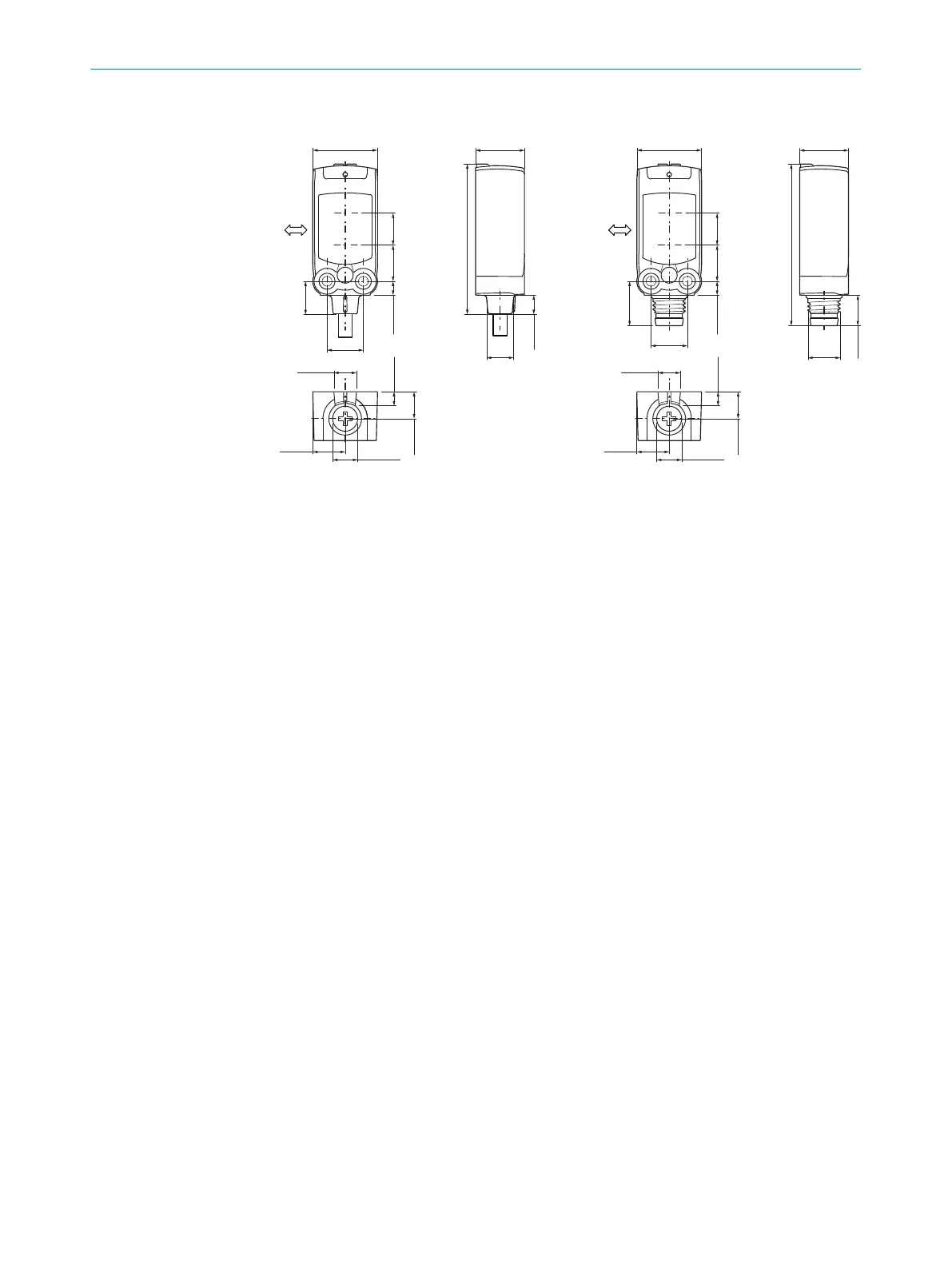
Figure 8: Dimensional drawing 1, cable
1
Preferred direction of the target
object
2
Center of optical axis, sender
3
Center of optical axis, receiver
4
M3 threaded mounting hole
5
Connection
6
LED indicator green: Supply voltage
active
7
LED indicator yellow: Status of
received light beam
8
Sensing range adjustment
3
1
2
8
67
4
5
16 (0.63) 12.1 (0.48)
9 (0.35)
M8
(0.31)
5.6 (0.22)
Ø 6.2 (0.24)
8 (0.32)
11 (0.43)
3.5 (0.14) 9 (0.35) 8 (0.31)
40.1 (1.58)
7.6 (0.3)
3.4 (0.13)
6.7 (0.26)
Figure 9: Dimensional drawing 2, male con‐
nector
TECHNICAL SPECIFICATIONS 11
8025665 / 2020-11-13 | SICK
Subject to change without notice
13