5 Mounting
Mount the sensor using a suitable mounting bracket (see the SICK range of acces‐
sories).
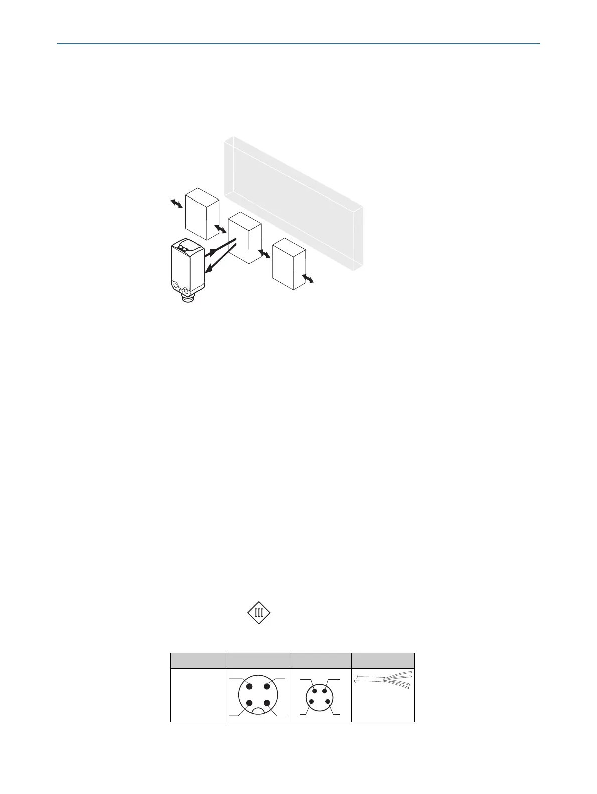
Figure 1: Alignment of the sensor relative to the object direction
Note the sensor’s maximum permissible tightening torque of < 0,4 Nm.
Note the preferred direction of the object relative to the sensor, cf. see figure 1, page 6.
6 Electrical installation
The sensors must be connected in a voltage-free state. The following information must
be observed, depending on the connection type:
– Male connector connection: Pin assignment
– Cable: Wire color
Only apply voltage/switch on the voltage supply once all electrical connections have
been established.
Explanations on connection diagram.
BN = brown
WH = white
BU = blue
BK = black
MF (pin 2 configuration) = external input, teach-in, switching signal
Q
L1
/C = switching output, IO-Link communication
Test = Test input
U
B
: 10 ... 30 V DC
Table 1: Electrical connection
x4 x2 xH
1 = BN
2 = WH
3 = BU
4 = BK
0.14 mm
2
AWG26
5 MOUNTING
6
8025665 / 2020-11-13 | SICK
Subject to change without notice