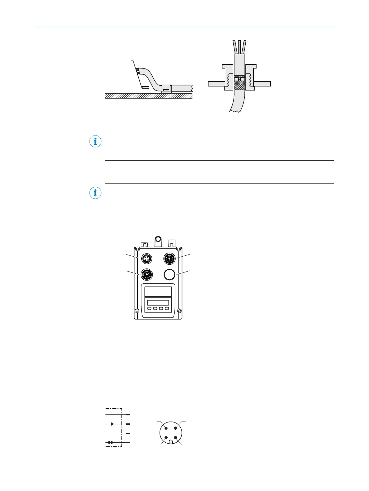
Figure 19: Shield connection in plastic housings
NOTE
Use an appropriate earthing method to prevent equipotential bonding currents flowing
through the cable shield.
6.3 Connecting the device electrically
NOTE
The connection diagram, and information on inputs and outputs can be found on the
type label on the device.
1. Ensure the voltage supply is not connected.
2. Connect the device according to the connection diagram.
Figure 20: Position of the electrical connections
1
Supply voltage (male connector, M12, 4-pin, A-coded)
2
Ethernet port 1 (female connector, M12, 4-pin, D-coded)
3
Ethernet port 2 (female connector, M12, 4-pin, D-coded)
4
Not assigned (spare)
6.4 Connection diagrams
6.4.1 MF1, MF2 supply voltage connection diagram
L+
MF2
M
MF1
1
2
4
wht
blu
brn
blk
3
Figure 21: MF1, MF2 supply voltage connection diagram
6 ELECTRICAL INSTALLATION
32
O P E R A T I N G I N S T R U C T I O N S | DL100 Pro PROFINET 8015069/19H9/2021-10-15 | SICK
Subject to change without notice