4.8 Operator control
4.8.1 Operator controls and display elements, settings, measuring ranges
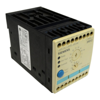
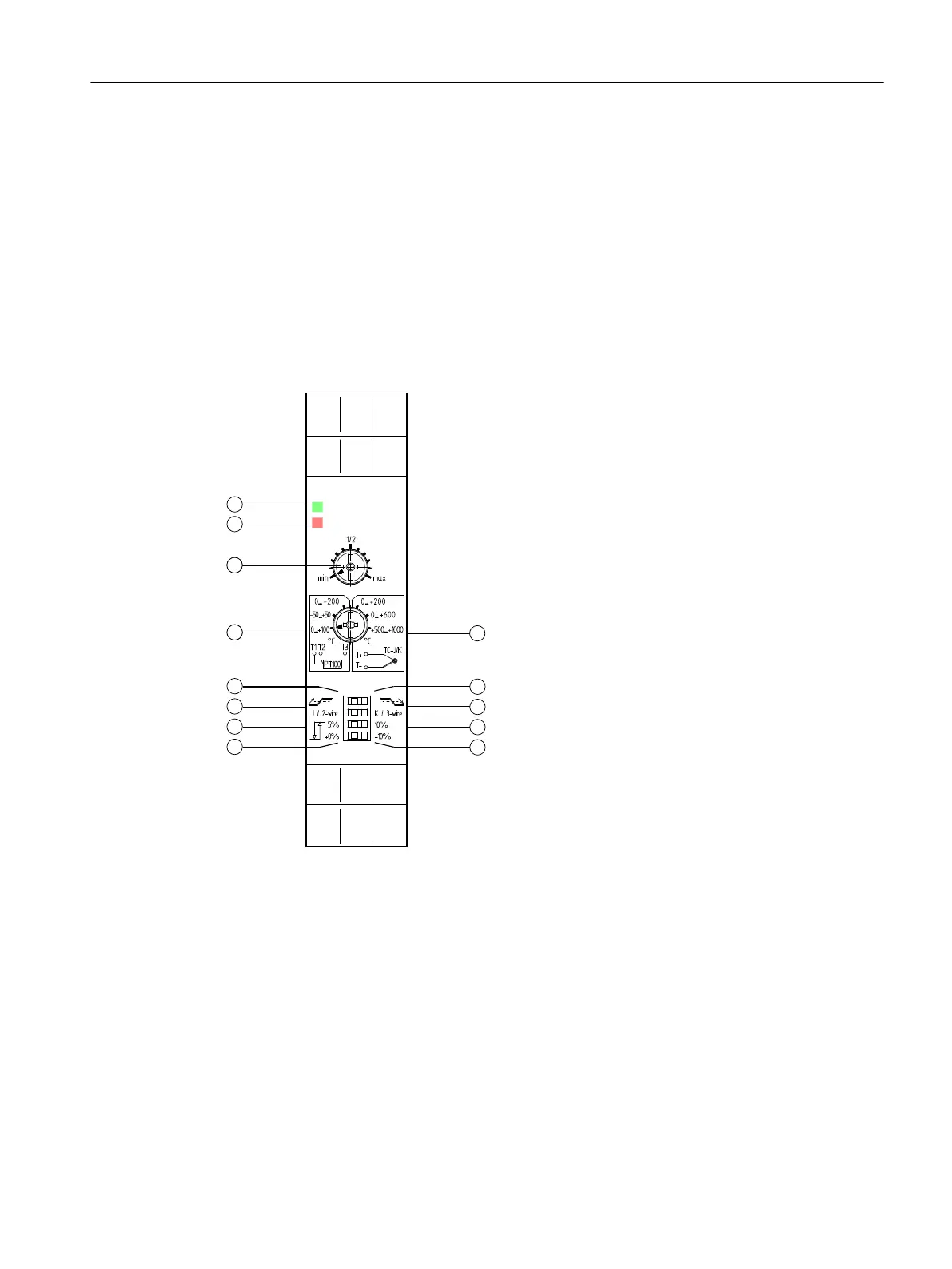
The analog devices are equipped with the following operator control and display elements on
the front:
A1(+)
T1/T T2/T+ T3
A2(-) A2(-)
12NC 11C 14NO
5HDG\
˽
1
55
7
8
9
2
3
4
13
12
11
10
56$$
56$$
56$:
56$:
56
Figure 4-1 Operator controls and display elements of the analog devices
① Extended hysteresis (+0%)
② Basic hysteresis (5%)
③ Sensor type (resistance sensors Pt100, 2-wire thermocouples type J)
④ Overshoot
⑤ Selection of temperature range (resistance sensors Pt 100)
⑥ Setting of the measured value ϑ1 (see Measuring ranges (Page 19))
⑦ Red diagnostics LED "Theta"
⑧ Green diagnostics LED "Ready"
⑨ Selection of thermocouple temperature measuring range (see table)
Analog devices
4.8 Operator control
3RS2 temperature monitoring relay
Equipment Manual, 02/2022, A5E42462552002A/RS-AB/002 21