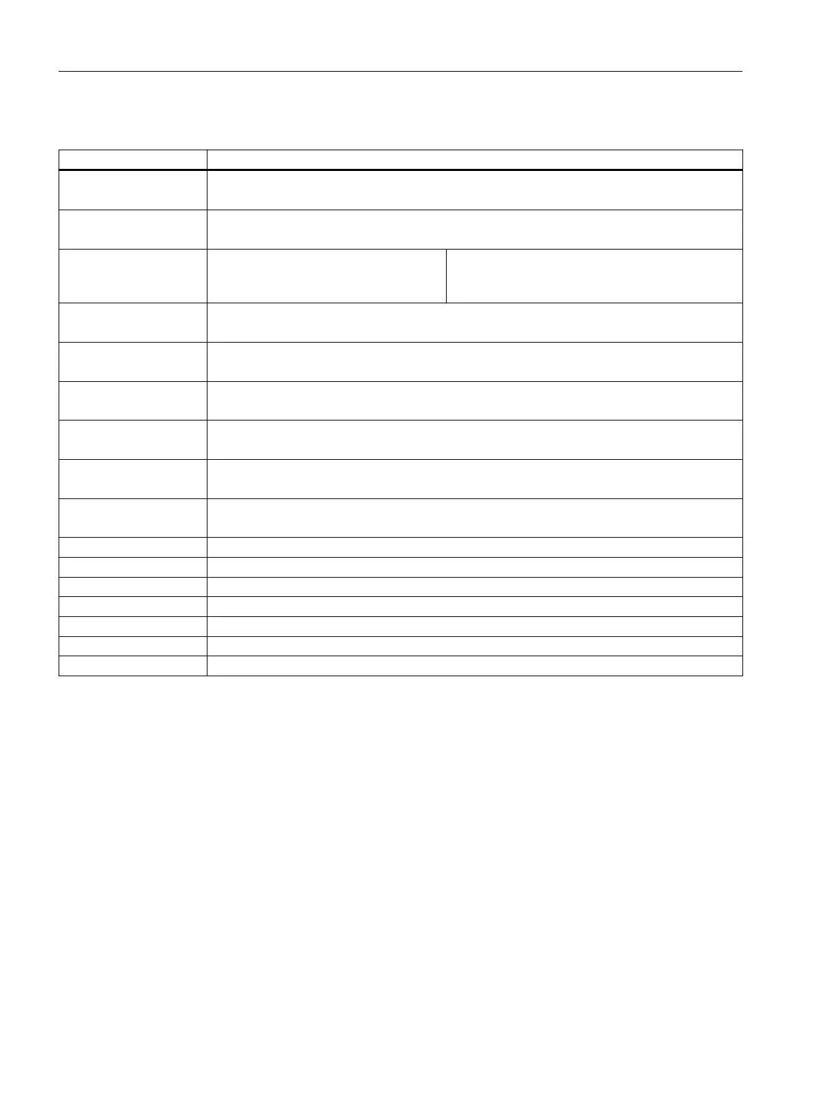
The table below contains an explanation of the terminal cover designations used:
Terminal designation Explanation
A1(+) Power supply (+)
Connection of 24V AC/DC or 24-240V AC/DC
A2(-) Power supply (-)
Connection of 24V AC/DC or 24-240V AC/DC
A2(-)/Y2 Power supply (-)
Connection of 24V AC/DC or
24-240V AC/DC
Common terminal for power supply and reset input
Y1 Reset input
Connection of oating NO contact between Y1 and Y2
1T1/1T2/1T3 Sensor input 1
Connection of thermocouples
2T1/2T2/2T3 Sensor input 2
Connection of thermocouples
3T1/3T2/3T3 Sensor input 3
Connection of resistance sensors
AI(+) Analog input (+)
Connection 4 mA ... 20 mA
AI(-) Analog input (-)
Connection 4 mA ... 20 mA
L+ Power supply IO-Link device (+)
L- Power supply IO-Link device (-)
C/Q Serial communication interface IO-Link interface
11C/21C Root of the change-over relay
14NO/24NO NO contacts of the change-over contacts
12NC/22NC NC contacts of the change-over contacts
33NO/34NO NO contacts relay 3
11.5 Connection tool
The devices are equipped with either screw terminals or spring-type terminals.
The temperature monitoring relays can be adjusted with the following tool options:
Screw terminals
Screw terminals with ergonomic handling when using a standard screwdriver.
Connection
11.5 Connection tool
3RS2 temperature monitoring relay
78 Equipment Manual, 02/2022, A5E42462552002A/RS-AB/002