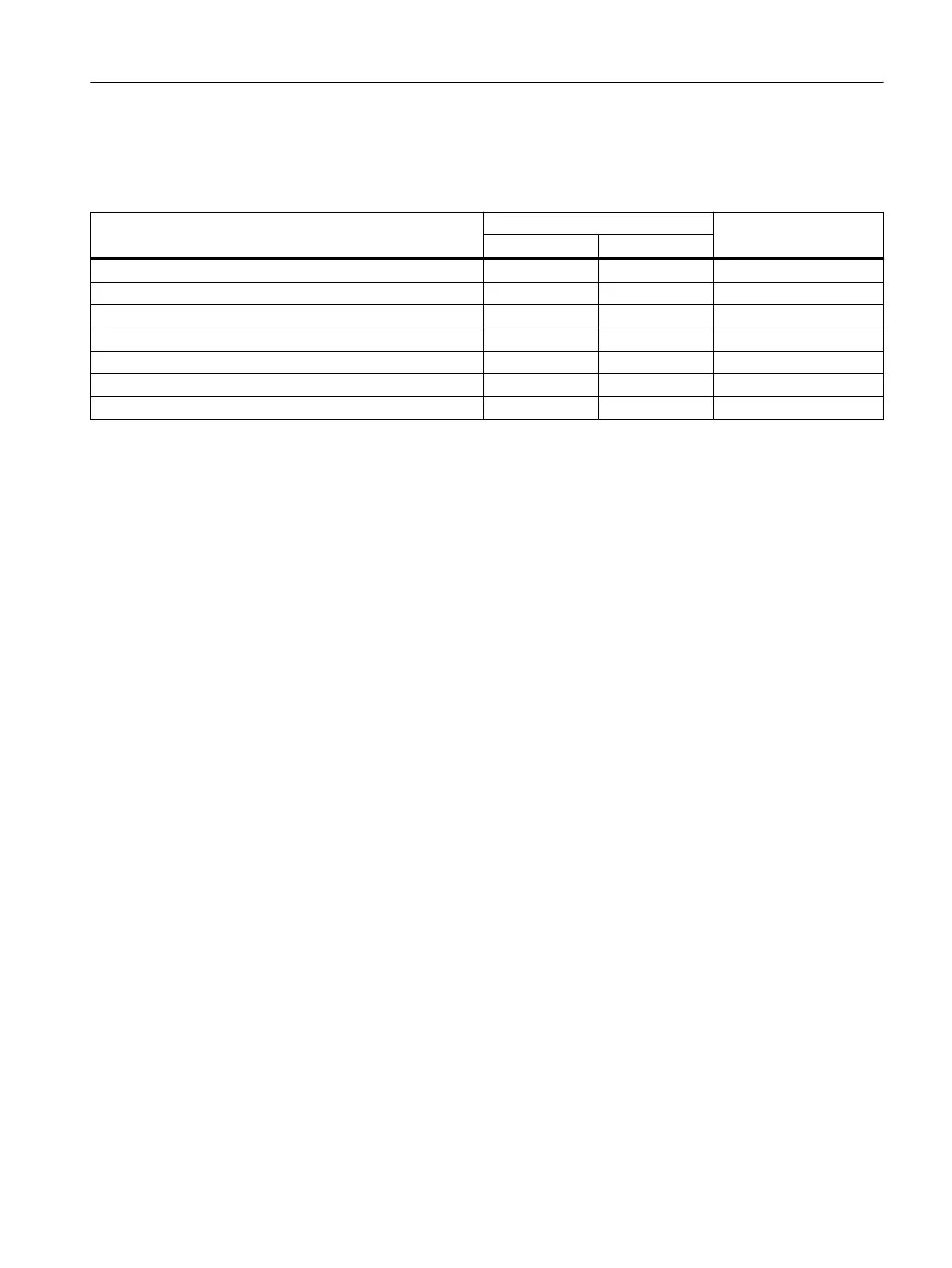
The table below indicates how the manufacturer-specic diagnostics are reported:
Table 6-2 Diagnostics via IO‑Link - Diagnostics and messages
Diagnostics and messages PII
1)
Data set 92
SF
2)
SW
3)
Invalid parameter x — x
Self-test error / internal error x — x
Limit for overshoot exceeded x — x
Limit for undershoot violated x — x
Temperature sensor 1, 2, or 3 - measuring range overshoot x — x
Temperature sensor 1, 2, or 3 - wire break x — x
Temperature sensor 1, 2, or 3 - short-circuit x — x
1) With the "process image input" (see Chapter "Process image output (PIQ) and input (PII)
(Page 102)"), you can determine via the group error (SF) bit or group warning (SW) bit in the user
program whether detailed information on diagnostics or messages is present in diagnostic data
set 92. If bit (= 1) is set, you can obtain detailed information on what caused a "group error" or
"group warning" by reading data set 92.
2) SF = group error: You can nd detailed information in diagnostics data set 92 (see Chapter
"Data set 92 - Diagnostics (Page 104)").
3) SW = group warning: You can nd detailed information in diagnostics data set 92 (see Chapter
"Data set 92 - Diagnostics (Page 104)").
x: Bit set
○: Not relevant
Digital devices with IO-Link
6.10 Diagnostics via IO‑Link
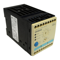
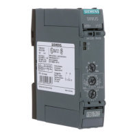
3RS2 temperature monitoring relay
Equipment Manual, 02/2022, A5E42462552002A/RS-AB/002 61