Logic operations
(continued)
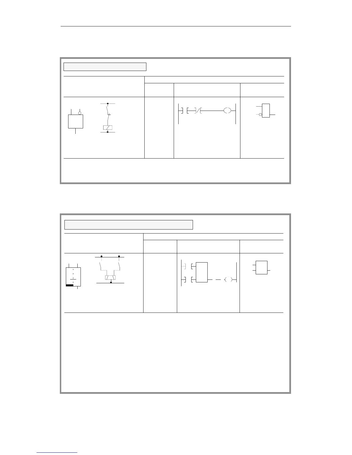
Set/reset operations
I 1.5 Q 3.0
I 1.5 I 1.6
Q 3.0
&
I 1.6
I 1.5
Q 3.0
A
I 1.5
AN I 1.6
= Q3.0
I 1.6
I 1.5
I 1.6 Q 3.0
&
Output Q 3.0 is "1" only when input I 1.5 has signal state "1"
state "0" (normally closed contact activated)
(normally open contact activated) and input I 1.6 has signal
Logical/circuit diagram
STEP 5 representation
Ladder Control system
Statement
list
Scan for signal state "0"
diagram flowchart
I 1.4 I 2.7
I 2.7
Q 3.5
I 1.4
Q 3.5
I 2.7 Q3.5
I 1.4
S
RQ
A I 2.7
I 1.4
Q 3.5
S
R
Q 3.5
A
I 2.7
I 1.4
Q3.5
R
S
Q R
S
11
10
Signal state "1" at input I 2.7 sets the flip-flop
(signal state "1" at output Q 3.5).
If the signal state at input I 2.7 changes to "0", the
state of output Q 3.5 is retained (i.e. the signal is latched).
If the signal state at input I 1.4 changes to "0", the
state of Q 3.5 is retained.
Signal state "1" at input I 1.4 resets the flip-flop
(signal state "0" at output Q 3.5).
When the set signal (input I 2.7) and the reset signal
(input I 1.4) are applied at the same time, the scan
operation programmed last (in this case AI 1.4)
remains in effect for the rest of the program (reset priority).
Logical/circuit diagram
STEP 5 representation
Ladder Control system
Statement
list
RS flip-flop for a latching signal output
diagram flowchart
Programming Examples in the STL, LAD and CSF Methods of Representation
CPU 948 Programming Guide
C79000-G8576-C848-04
3 - 37