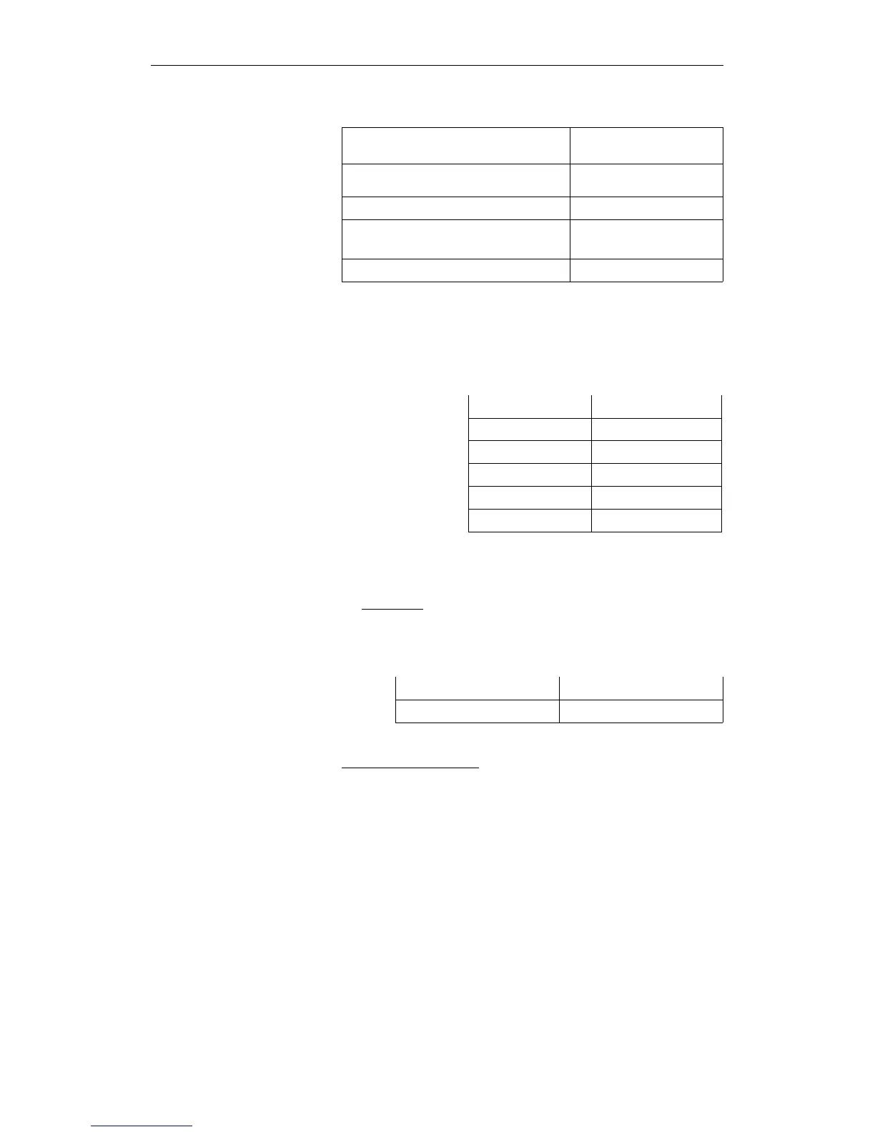
The parameters have the following significance and range of values :
Parameter Permitted range of values
Data block type (source and destination) 1 = DB
2 = DX
Data block no. (source and destination) 3 to 255
No. of 1st data word (source and
destination)
0 to 4090
Number of data words 1 to 4091
Data field in flag area
If you set up the data field in a flag area, you must take into account the
following assignment of data field words to flag bytes. ’x’ is the
parameter "no. of the 1st data field word" which you must enter in
ACCU-1-L when OB 182 is called:
Bit no. 15 87 0
1st data field word Flag byte x Flag byte x+1
2nd data field word Flag byte x+2 Flag byte x+3
3rd data field word Flag byte x+4 Flag byte x+5
4th data field word Flag byte x+6 Flag byte x+7
5th data field word Flag byte x+8 Flag byte x+9
2. Accumulators
2a)
ACCU-2-L
ACCU-2-L contains information about the data field used. It must
have the following structure:
Bit no. 15 8 7 0
Address area type Data block no.
Parameters in ACCU-2-L
Address area type,
Permitted values: 1 = DB data block
2 = DX data block
3 = F flag area
4 = S flag area
Data block no.,
Permitted values: 3 to 255 (only with address area type ’1’ or ’2’;
with address area type ’3’ or ’4’ irrelevant)
OB 182: Copy Data Area
CPU 948 Programming Guide
6 - 60 C79000-G8576-C848-04