2 Installation
MICROMASTER 430 Operating Instructions
22 6SE6400-5AC00-0BP0
Humidity Range
Relative air humidity ≤ 95 % Non-condensing
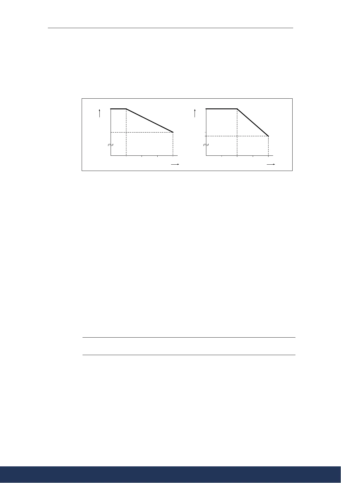
Altitude
If the inverter is to be installed at an altitude > 1000 m or > 2000 m above sea
level, derating will be required:
80
100
0 1000
2000
3000 4000
Permissible output current
%
Installation altitude in m above sea level
Permissible input voltage
80
100
0 1000
2000
3000 4000
%
Installation altitude in m above sea level
77
Figure 2-3 Installation altitude
Shock and Vibration
Do not drop the inverter or expose to sudden shock. Do not install the inverter in an
area where it is likely to be exposed to constant vibration.
Mechanical strength to DIN IEC 68-2-6
Ø Deflection: 0.075 mm (10 ... 58 Hz)
Ø Acceleration: 9.8 m/s
2
(> 58 ... 500 Hz)
Electromagnetic Radiation
Do not install the inverter near sources of electromagnetic radiation.
Atmospheric Pollution
Do not install the inverter in an environment, which contains atmospheric pollutants
such as dust, corrosive gases, etc.
Water
Take care to site the inverter away from potential water hazards, e.g. do not install
the inverter beneath pipes that are subject to condensation. Avoid installing the
inverter where excessive humidity and condensation may occur.
Installation and cooling
CAUTION
The inverters MUST NOT be mounted horizontally.
The inverters can be mounted without any clearance at either side.
The following clearances above and below the inverter are necessary:
Ø FS C 100 m
Ø FS D, E 300 mm
Ø FS F 350 mm
When mounting one inverter above the other, the ambient operating temperature
must be adhered to. Make sure that the cooling vents in the inverter are positioned
correctly to allow free movement of air.
www.eltra-trade.com
+421 552 601 099
info@eltra-trade.com